Tolerance In Engineering Drawing
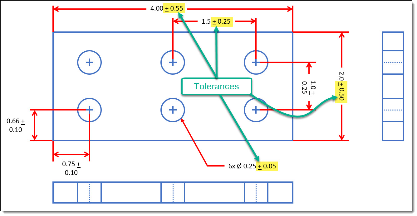
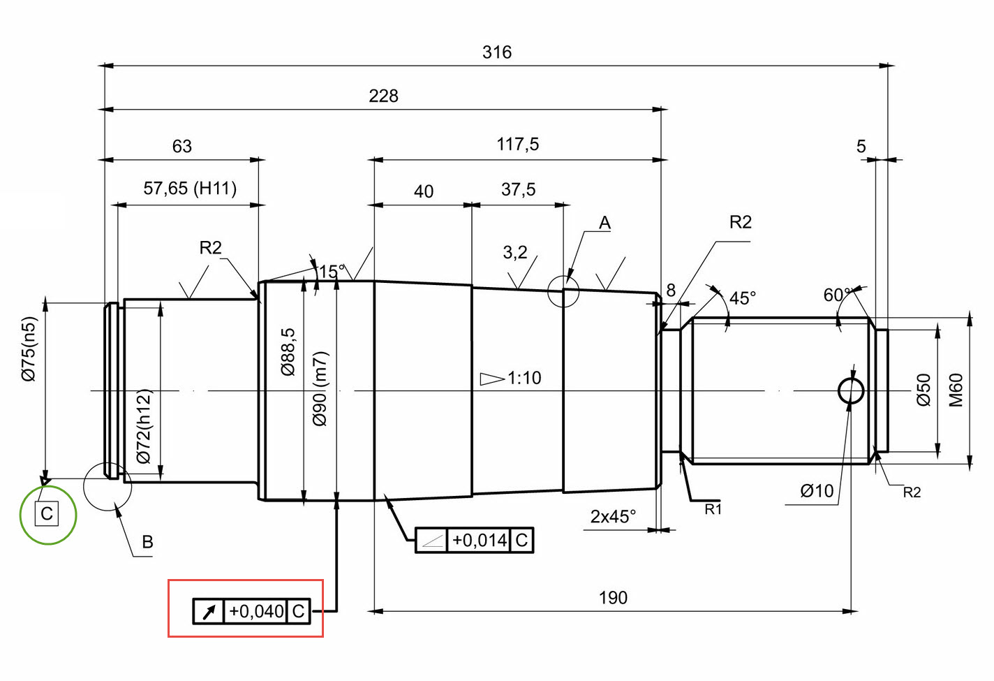
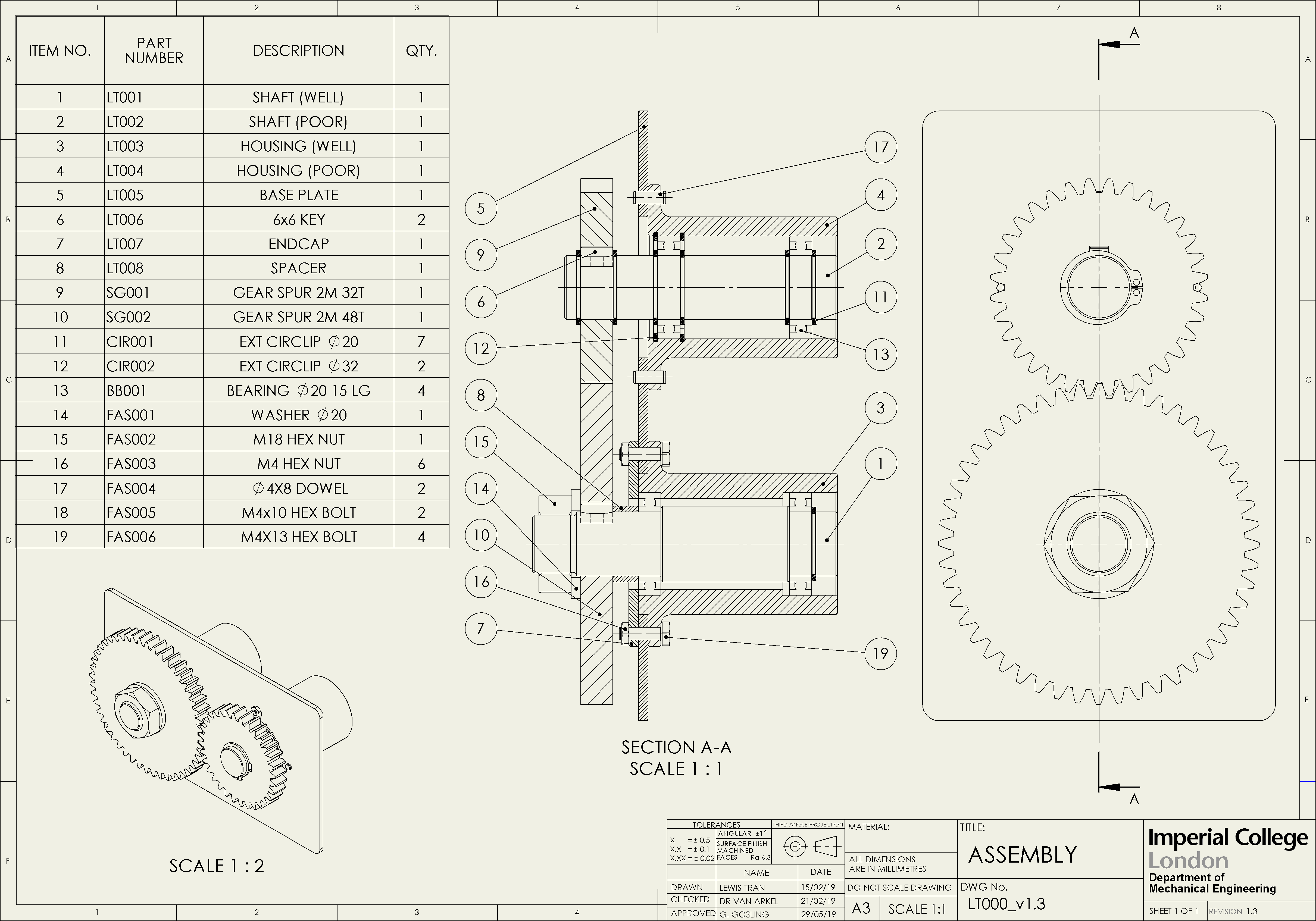
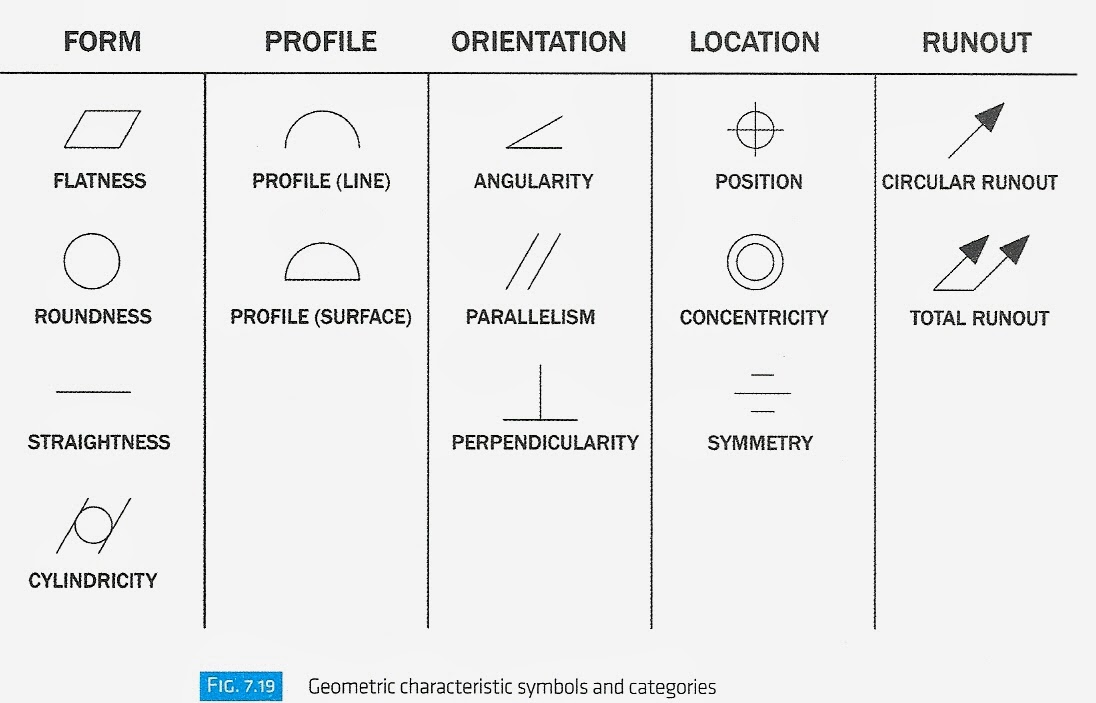
Tolerance In Engineering Drawing - Dimension tolerance is the amount of variation allowed in a size. A measured value or physical property of a material, manufactured object, system, or service; Web the drawing shows 0.43 in. This section outlines the scope and intent of the standard, which we have described in detail above. This puts inspection and cnc programming permanently at odds by 0.005 in. Find out in this preview for the engineering drawings fundamentals course from thors elearning s. Web tolerance is the total amount a dimension may vary and is the difference between the upper (maximum) and lower (minimum) limits. Furthermore, we are going to learn. Web in this video, we are going to learn about tolerances in engineering drawing! In particular, tolerances are assigned to mating parts in an assembly. It’s the basics of engineering tolerance. Dimension tolerance is the amount of variation allowed in a size. Web engineering tolerance is the permissible limit or limits of variation in: To 0.480 in.) might simply represent laziness, not function in terms of how the part is. Web engineering tolerances include dimension tolerance, shape tolerance, and position tolerance. Gd&t is a way of describing the dimensions and tolerances that’s different from traditional coordinate measurement plus/minus tolerancing. 2.1 what is standard tolerancing & why it is essential? Entry of the tolerances on the drawing. We are going to look at what are tolerances and reasons for size variations. Scope of the applying tolerances. As another problem, the tolerable size allowed (0.380 in. From the table, we can see that the tolerance grade applies to a range of basic sizes. Find out in this preview for the engineering drawings fundamentals course from thors elearning s. A measured value or physical property of a material, manufactured object, system, or service; So if we have a. Web how do you determine the tolerance on a engineering drawing? Using gd&t results in a more accurate design, larger tolerances for less important design features, and cost savings for manufacturing. Entry of the tolerances on the drawing. Web an engineering drawing may include general tolerances in the form of a table or just a little note somewhere on the. Refers to the acceptable variation in sizes like lengths, widths, thicknesses, radii, etc. 7.9k views 2 years ago. From the table, we can see that the tolerance grade applies to a range of basic sizes. Web engineering tolerances include dimension tolerance, shape tolerance, and position tolerance. Gd&t is a way of describing the dimensions and tolerances that’s different from traditional. Furthermore, we are going to learn. Web engineering tolerance is the permissible limit or limits of variation in: Entry of the tolerances on the drawing. Web engineering tolerances include dimension tolerance, shape tolerance, and position tolerance. This puts inspection and cnc programming permanently at odds by 0.005 in. Other measured values (such as temperature, humidity, etc.); As a default tolerance, whereas the step file shows the nominal value of 0.425 in. So if we have a hole with a nominal size of 25 mm and a tolerance class of h7, we will fit into the 18…30 mm basic size group. Web 1 the basics: They can be applied. Web tolerance is the total amount a dimension may vary and is the difference between the upper (maximum) and lower (minimum) limits. As another problem, the tolerable size allowed (0.380 in. Web a tolerance class determines a range of values the final measurement can vary from the base measurement. So if we have a hole with a nominal size of. 2.1 what is standard tolerancing & why it is essential? Web tolerance is the total amount a dimension may vary and is the difference between the upper (maximum) and lower (minimum) limits. 4 deciphering the iso tolerance table. 2 the pivotal role of standard tolerancing in manufacturing. I discuss tolerances on engineering drawings. Entry of fit tolerances on the engineering drawing. From the table, we can see that the tolerance grade applies to a range of basic sizes. Web sections five through nine each describe tolerancing of one of the following fundamental categories: Determining a positive or a negative dimension direction. Web tolerance is the total amount a dimension may vary and is. In particular, tolerances are assigned to mating parts in an assembly. Web 1 the basics: Web how do you determine the tolerance on a engineering drawing? So if we have a hole with a nominal size of 25 mm and a tolerance class of h7, we will fit into the 18…30 mm basic size group. 1.1 tolerance range determination & implications for manufacturing. They can be applied to several conditions, including linear dimensions, angular dimensions, external radius, chamfer heights, etc. Web tolerance is the total amount a dimension may vary and is the difference between the upper (maximum) and lower (minimum) limits. Web geometric dimensioning and tolerancing is a set of rules and gd&t symbols used on a drawing to communicate the intent of a design, focusing on the function of the part. 7.9k views 2 years ago. This section outlines the scope and intent of the standard, which we have described in detail above. Form, orientation, location, profile, and runout. I discuss tolerances on engineering drawings. Web sections five through nine each describe tolerancing of one of the following fundamental categories: Dimension tolerance is the amount of variation allowed in a size. Entry of the tolerances on the drawing. Because it is impossible to make everything to an exact size, tolerances are used on production drawings to control the parts.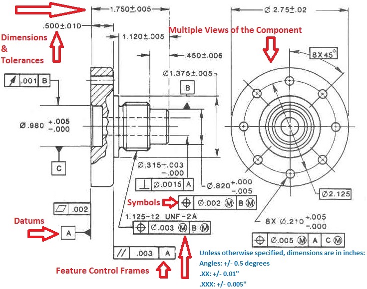
Types Of Tolerance In Engineering Drawing at GetDrawings Free download
Engineering Drawings & GD&T For the Quality Engineer

Tolerances A Brief Introduction EngineeringClicks
Types Of Tolerance In Engineering Drawing at
Engineering Tolerances Design Learning Objects
Types Of Tolerance In Engineering Drawing at GetDrawings Free download
Fit and Dimensional Tolerances Mechanical Engineering Drawing
Specifying Tolerance in Engineering Drawings Techno FAQ

Examples of Determining the Tolerance on an Engineering Drawing? ED
Types Of Tolerance In Engineering Drawing at
Gd&T Is A Way Of Describing The Dimensions And Tolerances That’s Different From Traditional Coordinate Measurement Plus/Minus Tolerancing.
Furthermore, We Are Going To Learn.
As A Default Tolerance, Whereas The Step File Shows The Nominal Value Of 0.425 In.
4 Deciphering The Iso Tolerance Table.
Related Post:
