Single Line Electrical Drawing
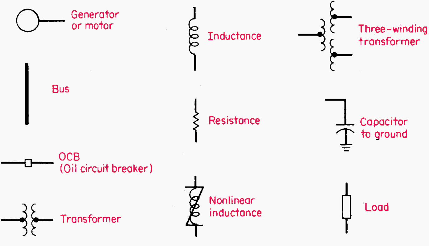
Single Line Electrical Drawing - Web single line diagrams are common types of schematics used in electrical wirings. For electric power networks an appropriate selection of graphic symbols is shown in figure 1 (common power symbols used in single line diagrams): A block diagram is a type of electrical drawings that represents the principle components of a complex system in the form of blocks interconnected by lines that represent their relation. By default, you'll draw a segmented line with an arrow at one end. Web a single line diagram is method of simplified representation of a three phase power system. Start drawing lines by clicking on the line tool at the top of the smartpanel. This video shows an example of how to create a single line diagram for electr. Its emphasis is on communicating the functions of the power equipment. We call this a shape connector. Transmission, distribution, and power transformers are also three phases. For electric power networks an appropriate selection of graphic symbols is shown in figure 1 (common power symbols used in single line diagrams): A single line can show all or part of a system. We will looking a normal set of plans o. It is used by electricians, engineers, and technicians to understand the electrical components and connections within a. Web this electrical one line diagram is the primary reference for maintenance and operations for lockout/tagout procedures, as well as for any engineering power system studies. Web single line diagrams are common types of schematics used in electrical wirings. Web by r jagan mohan rao. Start drawing lines by clicking on the line tool at the top of the smartpanel.. By default, you'll draw a segmented line with an arrow at one end. A single line in the diagram typically corresponds to more than one physical conductor: Transmission, distribution, and power transformers are also three phases. Start drawing lines by clicking on the line tool at the top of the smartpanel. Web single line diagram is the representation of a. Web the single line diagram (sld) is the most basic of the set of diagrams that are used to document the electrical functionality of the substation. In this post, i will show why you need an sld and how to make it. Web a single line diagram is method of simplified representation of a three phase power system. 27k views. Main components such as transformers, switches, and breakers are indicated by their standard graphic symbol. “a diagram which shows, by means of single lines and graphic symbols, the course of an electric circuit or system of circuits and the component devices or parts used therein.” Web in electrical engineering, a single line diagram is a simplified representation of an electrical. By default, you'll draw a segmented line with an arrow at one end. We call this a shape connector. Web this electrical one line diagram is the primary reference for maintenance and operations for lockout/tagout procedures, as well as for any engineering power system studies. In this post you’ll learn what is single line diagram and why do we need. In this post, i will show why you need an sld and how to make it. Web a single line diagram is method of simplified representation of a three phase power system. In this post you’ll learn what is single line diagram and why do we need it. It is the first step in preparing a critical response plan, allowing. It is a graphical representation of a circuit or. Web we usually depict the electrical distribution system by a graphic representation called a single line diagram (sld). For electric power networks an appropriate selection of graphic symbols is shown in figure 1 (common power symbols used in single line diagrams): Start drawing lines by clicking on the line tool at. It is used by electricians, engineers, and technicians to understand the electrical components and connections within a system. Main components such as transformers, switches, and breakers are indicated by their standard graphic symbol. We call this a shape connector. We will looking a normal set of plans o. Ladder diagram or line diagram. It is a graphical representation of a circuit or. Web single line diagram is the representation of a power system using simple symbols for each component. Web the single line diagram (sld) is the most basic of the set of diagrams that are used to document the electrical functionality of the substation. In this post, i will show why you. Electrical power grids primarily consist of. Web by r jagan mohan rao. Web the single line diagram (sld) is the most basic of the set of diagrams that are used to document the electrical functionality of the substation. It is a graphical representation of a circuit or. 27k views 10 months ago single line diagrams (sld) in this video, i'll explain how to read substation single line diagram (sld) in 5 simple steps. Web in electrical engineering, a single line diagram is a simplified representation of an electrical power system or electrical grid that shows the flow of electricity through the system. Main components such as transformers, switches, and breakers are indicated by their standard graphic symbol. It is the first step in preparing a critical response plan, allowing you to become thoroughly familiar with the electrical distribution system layout and design in your facility. Ladder diagram or line diagram. Our electrical power systems primarily contain three phases of ac circuits. Web by the end of this video will completely understand the ideals of the one line diagram from a electrical perspective. We will looking a normal set of plans o. You circuit diagram will basically visualize circuits as lines and the added symbols will indicate where switches and fusers may go. A single line in the diagram typically corresponds to more than one physical conductor: A block diagram is a type of electrical drawings that represents the principle components of a complex system in the form of blocks interconnected by lines that represent their relation. Start drawing lines by clicking on the line tool at the top of the smartpanel.
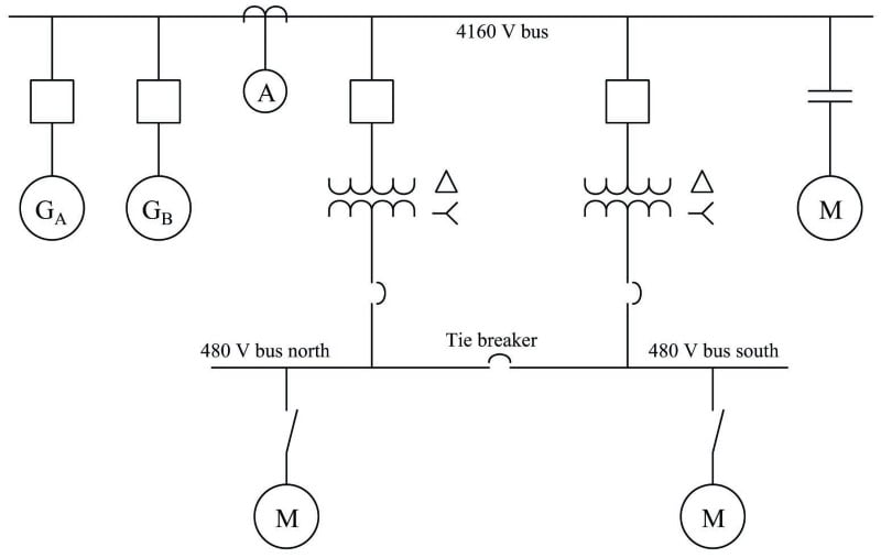
Single Line Diagram of Power Plant Power Systems
Understanding Substation Single Line Diagrams and IEC 61850 Process Bus
Electrical SingleLine Diagram Intelligent One Line Diagram ETAP

How to Read and Understand an Electrical Single Line Diagram?
Electrical Single Line Diagram Template (DWG) — LINE DRAW CAD LAB
how to prepare electrical single line diagram Wiring Diagram and
Learn to read and understand single line diagrams & wiring diagrams EEP
Singleline Electrical Diagrams Electric Power Measurement and
How To Calculate and Draw a Single Line Diagram For The Power System EEP
Electrical Single Line Diagram Part Two Electrical Knowhow
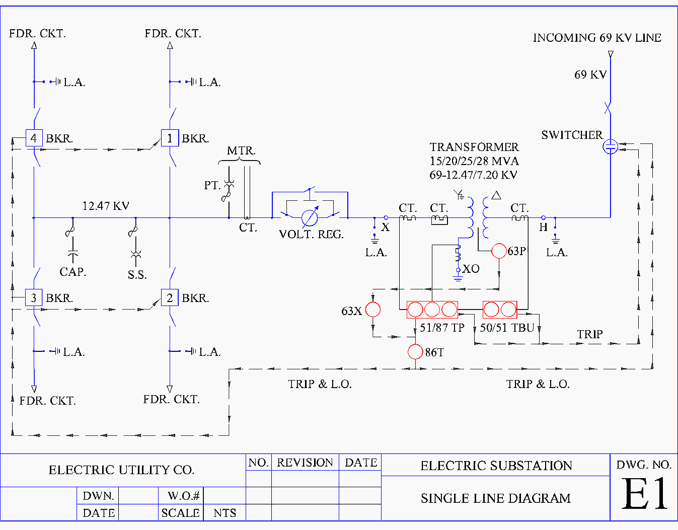
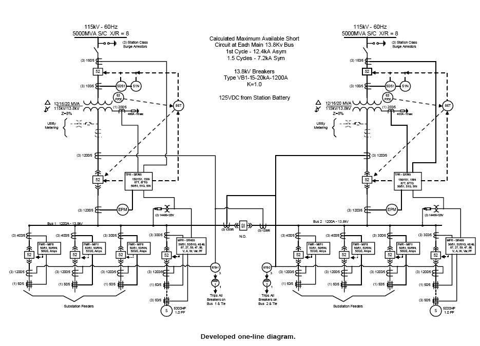
Web This Electrical One Line Diagram Is The Primary Reference For Maintenance And Operations For Lockout/Tagout Procedures, As Well As For Any Engineering Power System Studies.
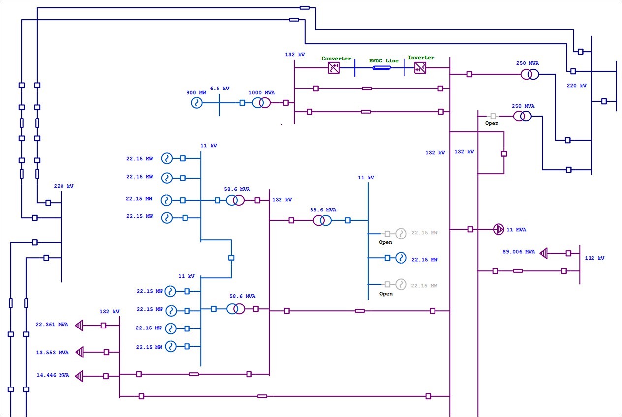
The Single Line Diagram Of A Power System Is Networked Show The Main Connections And Arrangement Of The System Components Along With Their Data (Such As Output Rating, Voltage, Resistance And Reactance, Etc.).
We Call This A Shape Connector.
In This Post You’ll Learn What Is Single Line Diagram And Why Do We Need It.
Related Post: