Sectional Views In Engineering Drawing
Sectional Views In Engineering Drawing - Cutting plane of an object. Used to improve clarity and reveal interior features of parts. Since they are used to set off a section, they must be drawn with care. This is especially true for the engineer. There are a number of different types of sectional views that can be drawn. Section lines are generally drawn at a 45° angle. In the figure a regular multiview drawing and a sectioned multiview drawing of the same part in the front view, the hidden features can be seen after sectioning. Sections normally comprise of two parts, firstly the section cut indicator with identification. Used to show where the object is being cut. Web when sketching an object or part that requires a sectional view, they are drawn by eye at an angle of approximately 45 degrees, and are spaced about 1/8” apart. A few of the more common ones are: Cutting plane of an object. Sections of objects with holes, ribs, etc. Web draw sectional views—the views that are projected by imagining a machine part to have been cut and a part of it removed. Sections normally comprise of two parts, firstly the section cut indicator with identification. Section views are used extensively to show features of an object or an assembly that are not easily visible from the exterior. Web when sketching an object or part that requires a sectional view, they are drawn by eye at an angle of approximately 45 degrees, and are spaced about 1/8” apart. Web section views sectional drawings are multiview technical. Since they are used to set off a section, they must be drawn with care. This is especially true for the engineer. Web the cut surfaces are identified by drawing section lines and the view thus obtained is called the “sectional view” or “view in section” of the remaining object. Web a section view cuts through the object to reveal. Isometric and orthographic views could show these parts using a “hidden line,” a dashed line that indicates internal components of the object, but a section view gives the manufacturing team a more detailed look at these internal structures. The detail of an object can be shown by drawing a limited number of carefully chosen views and showing external features of. In the figure, views a are standard multiview projections. Section lines are thin and the symbols (type of lines) are chosen according to the material of the object. See this and over 140+. This method can be used with both simple and complex objects and involves the use of a cutting plane that dictates what portion of the object you. The partial section views are used when the internal contour in certain areas wants to be exposed and when the full section would not reveal any additional details. 35k views 8 years ago cad & engineering drawing tutorials (software independent) an animated video attempting to help beginners understand the purpose for,. Isometric and orthographic views could show these parts using. Sectioned technical illustrations are used to describe interior features of complicated assemblies. A section is drawn in coordination with the plan and elevation of an object. Learners match drawings of sectional views with the names of the views. Sections normally comprise of two parts, firstly the section cut indicator with identification. Web when sketching an object or part that requires. Sections normally comprise of two parts, firstly the section cut indicator with identification. Web section views sectional drawings are multiview technical drawings that contain special views of a part or parts, views that reveal interior features. In the figure, views a are standard multiview projections. Web draw sectional views—the views that are projected by imagining a machine part to have. In the figure, views a are standard multiview projections. The partial section views are used when the internal contour in certain areas wants to be exposed and when the full section would not reveal any additional details. This is especially true for the engineer. This method can be used with both simple and complex objects and involves the use of. See this and over 140+. Web #engineering_drawing #sectional_views #orthographic_projection_with_3d this video deals with the engineering drawing of first year.it consists of half sectional and full sectional. Section of an object is cut by an imaginary cutting plane. Section views are used extensively to show features of an object or an assembly that are not easily visible from the exterior. In. Web kind of sections 1. 312k views 8 years ago industry blueprints. This method can be used with both simple and complex objects and involves the use of a cutting plane that dictates what portion of the object you want to remove to reveal a more complex interior. Often partial section is also called the breakout section. Sections normally comprise of two parts, firstly the section cut indicator with identification. Web the cut surfaces are identified by drawing section lines and the view thus obtained is called the “sectional view” or “view in section” of the remaining object. Web in this interactive object, learners examine sectional views used in engineering drawings. Web when sketching an object or part that requires a sectional view, they are drawn by eye at an angle of approximately 45 degrees, and are spaced about 1/8” apart. What they are and how to create them. A few of the more common ones are: Sections of objects with holes, ribs, etc. Since they are used to set off a section, they must be drawn with care. The horizontal lines (parallel lines) are drawn with a 30° angle to the horizontal axis and the vertical line of the parts are normal to the vertical axis or perpendicular to the horizontal axis. Web a section view cuts through the object to reveal hidden cuts or parts. Cutting plane of an object. Used to indicate where the cutting plane cuts the material.
Sectional views/ Sectional view in engineering drawing /Full sectional

Sectional View in Engineering Drawing YouTube

Sectional View in Engineering Drawing YouTube
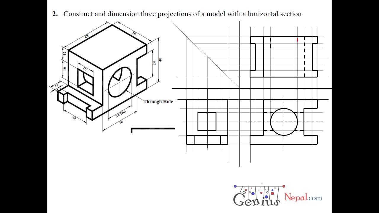
Engineering Drawing Tutorials/Orthographic and sectional views ( T 11.3
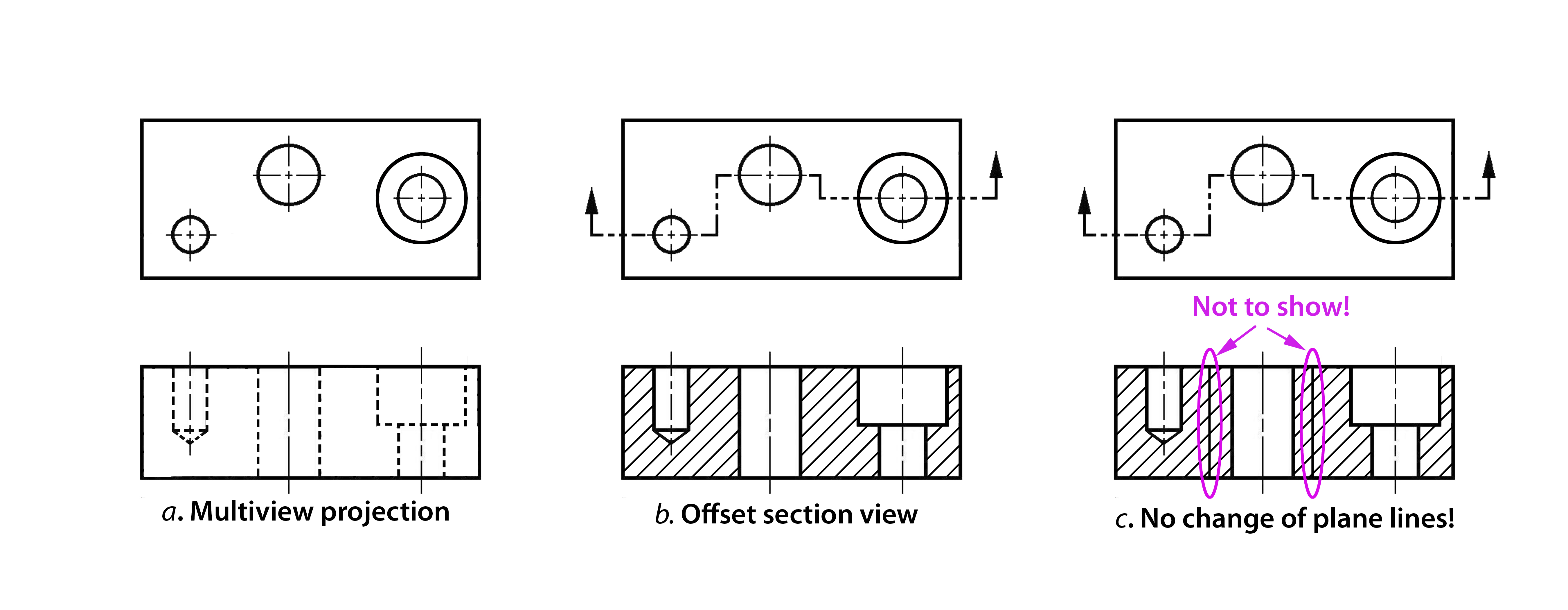
Sectioning Technique Engineering Design McGill University

Full Sectioning Problem 1 Engineering Drawing 9.1 YouTube
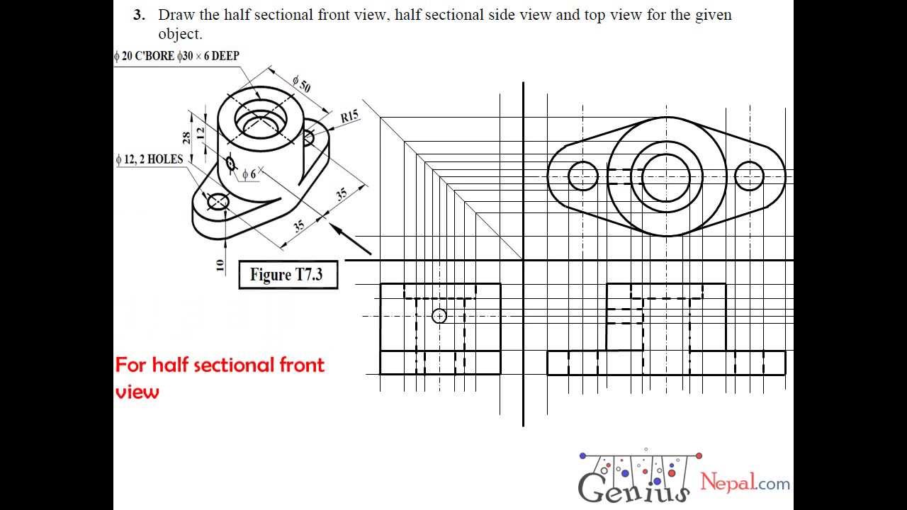
Engineering Drawing Tutorials/Sectional and Auxiliairy Views with Front
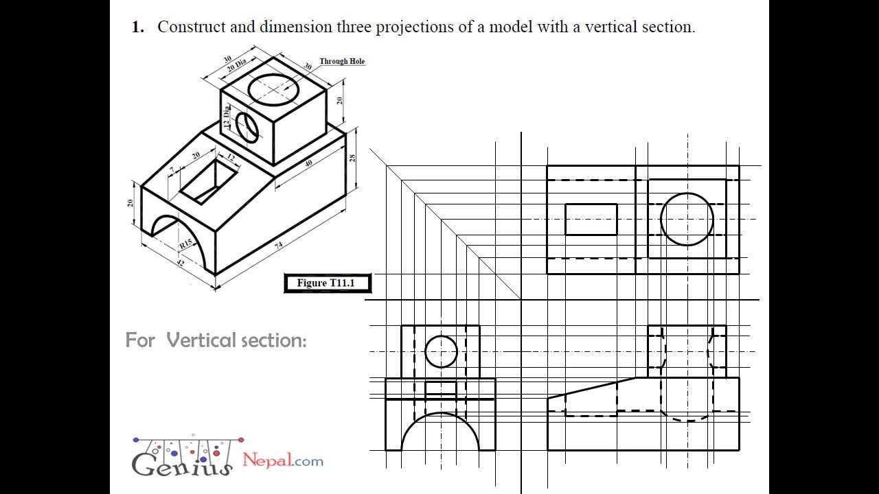
Engineering Drawing Tutorials/Orthographic and sectional views ( T 11.1

Sectional Views
Solved Engineering Drawing Section View Please help
35K Views 8 Years Ago Cad & Engineering Drawing Tutorials (Software Independent) An Animated Video Attempting To Help Beginners Understand The Purpose For,.
Isometric And Orthographic Views Could Show These Parts Using A “Hidden Line,” A Dashed Line That Indicates Internal Components Of The Object, But A Section View Gives The Manufacturing Team A More Detailed Look At These Internal Structures.
Web Theory Of Sectioning:
Section Of An Object Is Cut By An Imaginary Cutting Plane.
Related Post: