Potentiometer Drawing
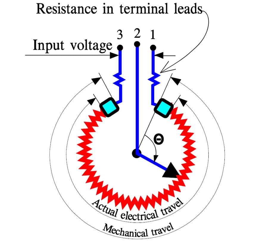
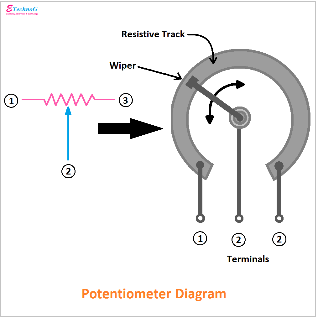
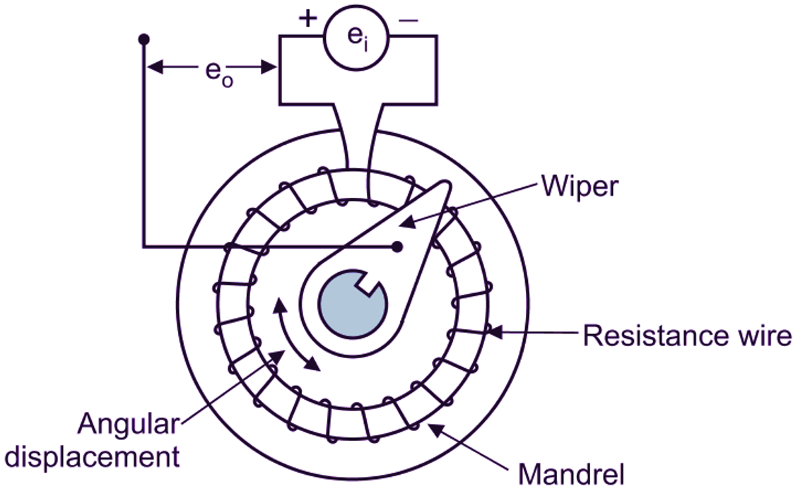
Potentiometer Drawing - For convenience, its terminals are labeled a and b for the two ends, and w for the wiper arm. Web it is an electric component used to measure the unknown voltage by comparing it with the known one, which can be drawn by a cell or any of the other supply sources. Web potentiometer principle (logic) & working. Web a potentiometer is an instrument for measuring voltage or 'potential difference' by comparison of an unknown voltage with a known reference voltage. Web in a circuit diagram, a potentiometer is represented by one of the two symbols below: We will see what is a potentiometer, its construction and symbol, its working, different types of potentiometers, application of potentiometer as rheostat and voltage divider and also potentiometer taper. The word ‘potentiometer’ is the combination of potential difference and metering. Schematic symbol for a potentiometer, with labels. The voltage supply is connected across terminals 1 and 3, positive lead to terminal one while negative lead to terminal three. Web in the circuit diagram shown below, the terminals of the potentiometer are marked 1, 2 and 3. Web since a potentiometer measures voltage, it can also be used to determine current simply by measuring the voltage drop produced by the unknown current piling through a known standard resistance.the potentiometer is extensively used for a calibration of voltmeters and ammeters and has, in fact, become the standard for the. In this tutorial, we will learn about potentiometers. Carefully. Two terminals (the blue and green) are connected to a resistive element and the third terminal (the black one) is connected to an adjustable wiper. Web it is an electric component used to measure the unknown voltage by comparing it with the known one, which can be drawn by a cell or any of the other supply sources. Web this. Svg png jpg dxf dwg. In a potentiometer, the entire input voltage is applied across the whole length of the resistor, and the output voltage is the voltage drop between the fixed and sliding contact as shown below. Identify the 3 main terminals sticking out of the middle of the pot. For convenience, its terminals are labeled a and b. The word ‘potentiometer’ is the combination of potential difference and metering. What does a potentiometer do and how does it work? The grabcad library offers millions of free cad designs, cad files, and 3d models. Potentiometers work by varying the position of a sliding contact across a uniform resistance. Web cutaway drawing of potentiometer showing parts: How does a potentiometer work? What does a potentiometer do and how does it work? (a) shaft, (b) stationary carbon composition resistance element, (c) phosphor bronze wiper, (d) shaft attached to wiper, (e, g) terminals connected to ends of resistance element, (f) terminal connected to wiper. The voltage supply is connected across terminals 1 and 3, positive lead to terminal. Web cutaway drawing of potentiometer showing parts: Web in a circuit diagram, a potentiometer is represented by one of the two symbols below: A pot can be visualized as two resistors in sequence with a tap between them. Web potentiometer symbol and pinout diagram (trim, rotary) by ankit negi. Potentiometers are adjustable resistors used in circuits for many things, such. The potentiometer is a device that was developed in the early days of electronics development. These devices have application in voltage di. Join the grabcad community today to gain access and download! The voltage supply is connected across terminals 1 and 3, positive lead to terminal one while negative lead to terminal three. For convenience, its terminals are labeled a. Svg png jpg dxf dwg. Carefully build this circuit on a breadboard or other convenient medium. Web this english language video describe potentiometer circuit as voltage measuring instrument. Web in the circuit diagram shown below, the terminals of the potentiometer are marked 1, 2 and 3. Web it is an electric component used to measure the unknown voltage by comparing. Web what is a potentiometer? Potentiometers are adjustable resistors used in circuits for many things, such as to control the volume of an amplifier, control the brightness of a. Web potentiometer principle (logic) & working. Last updated on april 6th, 2024 at 12:04 pm. Web this electronics video tutorial provides a basic introduction into potentiometers which are variable resistors. These devices have application in voltage di. If a sensitive indicating instrument is used, very little current is drawn from the source of the unknown voltage. In this tutorial, we will learn about potentiometers. The first terminal, or terminal 1, is your ground. The e.m.f.s are measured directly with the potentiometer in terms of the e.m.f. Web in the circuit diagram shown below, the terminals of the potentiometer are marked 1, 2 and 3. Web it is an instrument used for measuring the un known e.m.f., or potential difference by balancing it wholly or partially by a source of current in the network of known characteristics. This article will showcase use cases of potentiometers, as well as teach you how to connect and read data from them. The voltage supply is connected across terminals 1 and 3, positive lead to terminal one while negative lead to terminal three. Potentiometers work by varying the position of a sliding contact across a uniform resistance. Web this electronics video tutorial provides a basic introduction into potentiometers which are variable resistors. Web draw the schematic diagram for the circuit to be analyzed. The terminal 2 is connected to the wiper. Web cutaway drawing of potentiometer showing parts: (a) shaft, (b) stationary carbon composition resistance element, (c) phosphor bronze wiper, (d) shaft attached to wiper, (e, g) terminals connected to ends of resistance element, (f) terminal connected to wiper. Join the grabcad community today to gain access and download! We will see what is a potentiometer, its construction and symbol, its working, different types of potentiometers, application of potentiometer as rheostat and voltage divider and also potentiometer taper. Web this english language video describe potentiometer circuit as voltage measuring instrument. Web what is a potentiometer? The first terminal, or terminal 1, is your ground. Potentiometer working can be explained when the potentiometer is understood.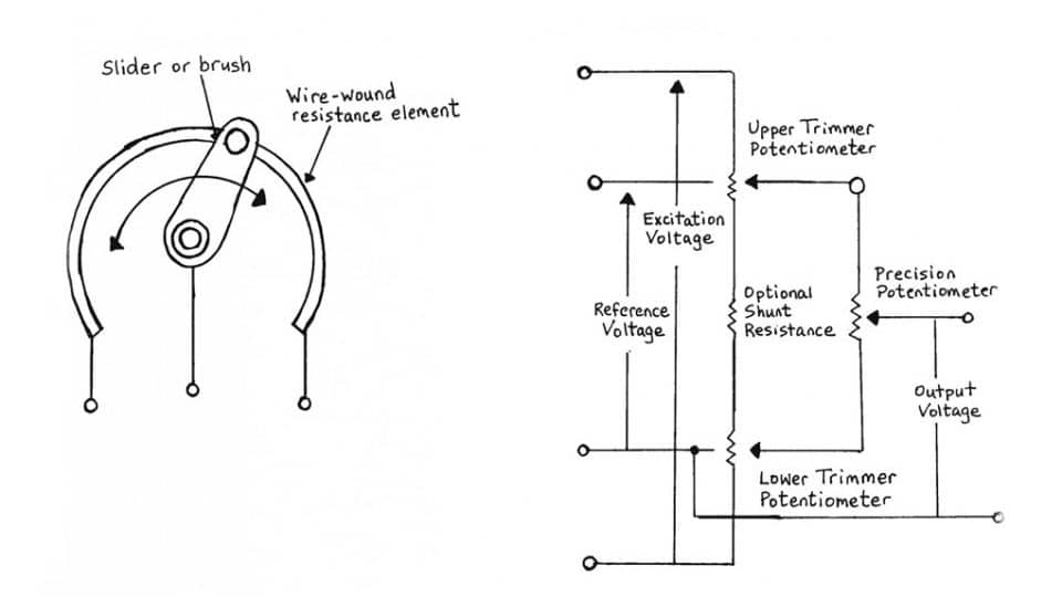
Potentiometers Basic Principles

Principle construction and working of potentiometer Physics Vidyapith ️
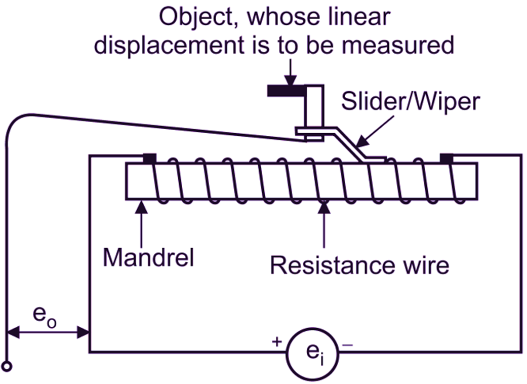
What is Linear Potentiometer? Working, Diagram & Explanation
Potentiometers Basic Principles
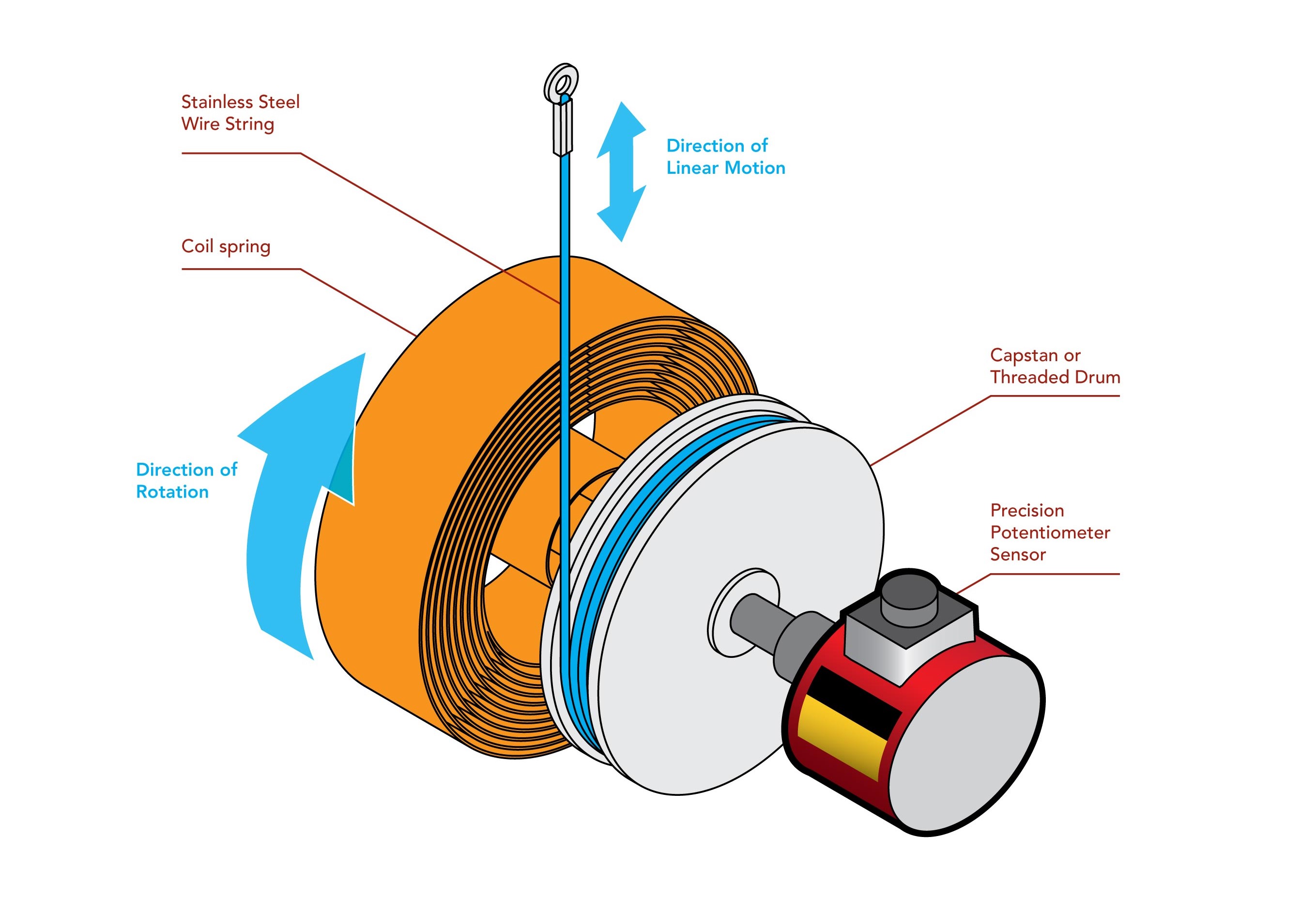
String Potentiometer Sensor FUTEK
![Arduino Potentiometer with Multiple LEDs [Tutorial] The Robotics BackEnd](https://roboticsbackend.com/wp-content/uploads/2021/09/arduino_circuit_potentiometer_multiple_leds.png)
Arduino Potentiometer with Multiple LEDs [Tutorial] The Robotics BackEnd
8 Pin Potentiometer Wiring Diagram

1/4" Smooth Shaft Potentiometer Right Angle PCB
(a) Annotated potentiometer schematic symbol. (b) Separation of the
What is Rotary Potentiometer? Working, Diagram & Explanation
Web The Schematic Symbol For A Basic Potentiometer Is Shown In Figure 3.8.3.
Last Updated On April 6Th, 2024 At 12:04 Pm.
The Grabcad Library Offers Millions Of Free Cad Designs, Cad Files, And 3D Models.
Web Potentiometer Principle (Logic) & Working.
Related Post: