Pid Drawings
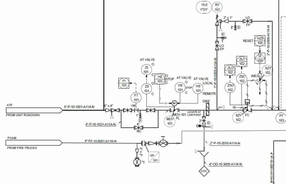
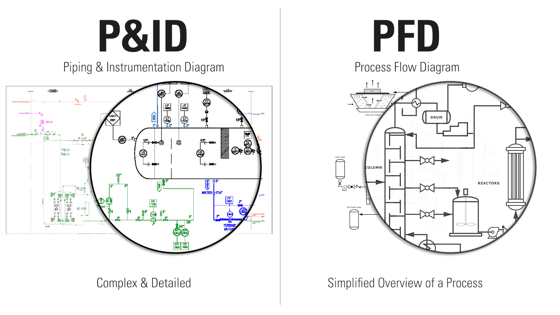
Pid Drawings - P&ids are used to develop guidelines and standards for facility operation. P&id is more complex than pfd and includes lots of details. Function and purpose of p&ids. It shows the equipment used in the process, and all of the signals required to measure and control the process. Web a piping and instrumentation diagram (p&id or pid) is a detailed diagram in the process industry which shows the piping and process equipment together with the instrumentation and control devices. Web in this video, you will learn the basics of piping and instrumentation diagrams (also called p&id drawings).#pipingandinstrumentation #processcontrol #instru. Web p&id drawing is a schematic representation of instrumentations, control systems, and pipelines used in any process development plant. Web the piping and instrumentation diagram (p&id) is a graphical representation of the actual process plant using various symbols that represent actual equipment. Web what is a p&id drawing? You will learn how to read p&id and pefs with the help of the actual plant drawing. It shows the equipment used in the process, and all of the signals required to measure and control the process. You will learn how to read p&id and pefs with the help of the actual plant drawing. It is a detailed diagram in the process industry that shows all piping including physical sequences of branches, reducers, valves, equipment, instrumentation and. Web what is a p&id drawing? It shows the equipment used in the process, and all of the signals required to measure and control the process. A p&id uses simple graphics to represent complex processes and convey the flow of material through a process. It is the basic training document to explain the process details to operation guys,. It's a. Web what is a p&id drawing? A piping and instrumentation diagram, or p&id, shows the piping and related components of a physical process flow. Function and purpose of p&ids. Web in this video, you will learn the basics of piping and instrumentation diagrams (also called p&id drawings).#pipingandinstrumentation #processcontrol #instru. It shows the equipment used in the process, and all of. Your list should include all piping elements, including the order and placement of: It uses symbols to represent process equipment such as sensors and controllers. P&ids are used to develop guidelines and standards for facility operation. It is also called as mechanical flow diagram (mfd). Every symbol contains letters and a number. Your list should include all piping elements, including the order and placement of: It is a detailed diagram in the process industry that shows all piping including physical sequences of branches, reducers, valves, equipment, instrumentation and control interlocks. Web what is a p&id drawing? It shows the equipment used in the process, and all of the signals required to measure. P&id is short for “piping and instrumentation diagram”. Remember that p&ids represent the hardware and software necessary to design, build, and run a process industry facility. Your list should include all piping elements, including the order and placement of: P&id is more complex than pfd and includes lots of details. A piping and instrumentation diagram, or p&id, shows the piping. It is a detailed diagram in the process industry that shows all piping including physical sequences of branches, reducers, valves, equipment, instrumentation and control interlocks. Web in this video, you will learn the basics of piping and instrumentation diagrams (also called p&id drawings).#pipingandinstrumentation #processcontrol #instru. Web p&id drawing is a schematic representation of instrumentations, control systems, and pipelines used in. Remember that p&ids represent the hardware and software necessary to design, build, and run a process industry facility. P&id is more complex than pfd and includes lots of details. Web in this video, you will learn the basics of piping and instrumentation diagrams (also called p&id drawings).#pipingandinstrumentation #processcontrol #instru. It shows the equipment used in the process, and all of. It shows the equipment used in the process, and all of the signals required to measure and control the process. Remember that p&ids represent the hardware and software necessary to design, build, and run a process industry facility. A p&id uses simple graphics to represent complex processes and convey the flow of material through a process. It's a simple way. It's a simple way of using lines and symbols to tell the story of how liquids and gases move around, and how machines control them. Web p&id drawing, or piping and instrumentation diagrams, is like a special map that shows how pipes and instruments work together in factories and plants. It shows the equipment used in the process, and all. Web p&id drawing is a schematic representation of instrumentations, control systems, and pipelines used in any process development plant. It is a detailed diagram in the process industry that shows all piping including physical sequences of branches, reducers, valves, equipment, instrumentation and control interlocks. Web here, i have tried to explain p&id and pefs in an easy way. It’s most commonly used in the engineering field. The piping and instrumentation diagram is also known as the process engineering flow scheme, pefs. You will learn how to read p&id and pefs with the help of the actual plant drawing. P&id is more complex than pfd and includes lots of details. P&ids are used to develop guidelines and standards for facility operation. Web p&id drawing, or piping and instrumentation diagrams, is like a special map that shows how pipes and instruments work together in factories and plants. Web a piping and instrumentation diagram (p&id or pid) is a detailed diagram in the process industry which shows the piping and process equipment together with the instrumentation and control devices. It shows the equipment used in the process, and all of the signals required to measure and control the process. P&ids are foundational to the maintenance and modification of the process that it graphically represents. Every symbol contains letters and a number. Web the piping and instrumentation diagram (p&id) is a graphical representation of the actual process plant using various symbols that represent actual equipment. It's a simple way of using lines and symbols to tell the story of how liquids and gases move around, and how machines control them. Your list should include all piping elements, including the order and placement of:
P&ID Document Reading Example Instrumentation Tools

Learn How to Read P&ID Drawings A Complete Guide
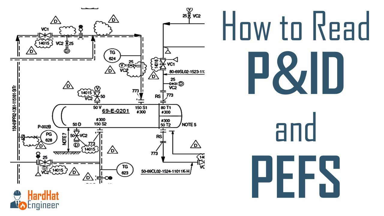
How to Read P&ID Drawing A Complete Tutorial YouTube
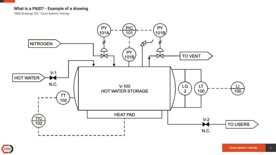
P&ID Drawings 101 — Corso Systems
Learn How to Read P&ID Drawings A Complete Guide
How to Read Oil and Gas P&ID Symbols Kimray
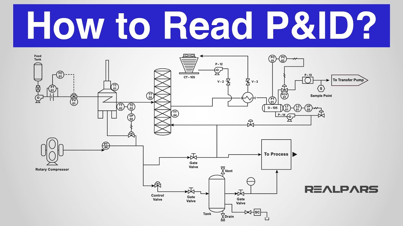
How to Read a P&ID? (Piping & Instrumentation Diagram) YouTube

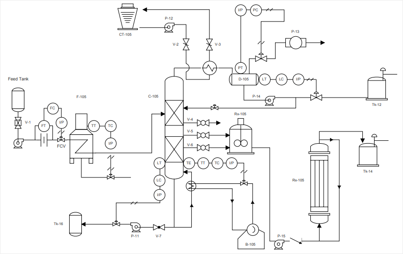
How to Read and Interpret Piping and Instrumentation Diagrams (P&ID) Learning Instrumentation

P & ID Diagram. How To Read P&ID Drawing Easily. Piping & Instrumentation Diagram Explained
How to Read a P&ID Drawing Quickly and Easily Edraw Max
To Create Such A Comprehensive Design, Start By Listing The Elements In A Standard P&Id.
P&Id Is Short For “Piping And Instrumentation Diagram”.
Web In This Video, You Will Learn The Basics Of Piping And Instrumentation Diagrams (Also Called P&Id Drawings).#Pipingandinstrumentation #Processcontrol #Instru.
It Is Also Called As Mechanical Flow Diagram (Mfd).
Related Post: