One Line Electrical Drawings
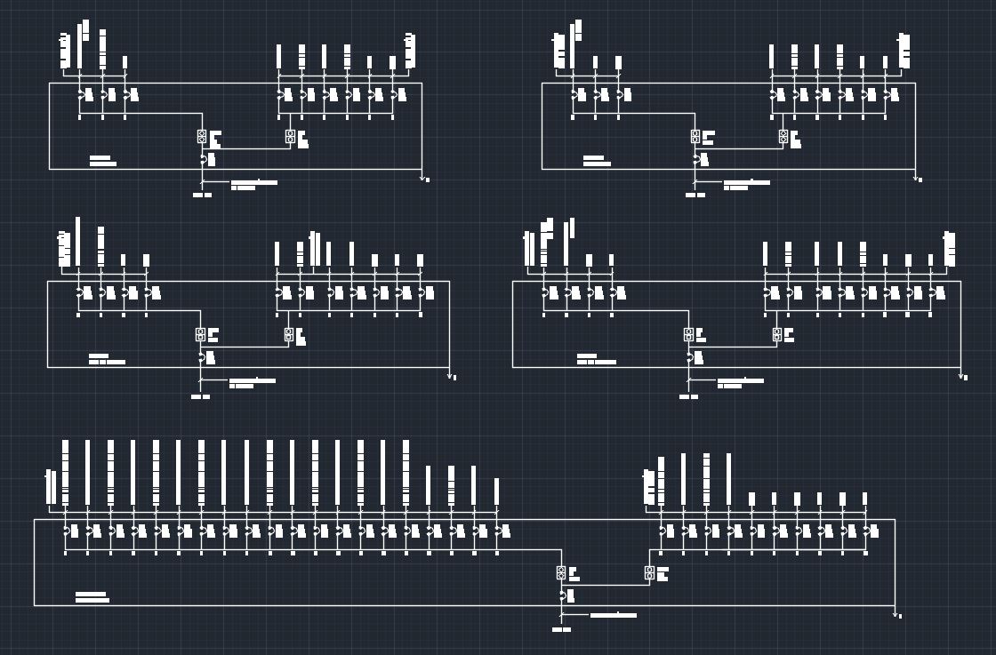
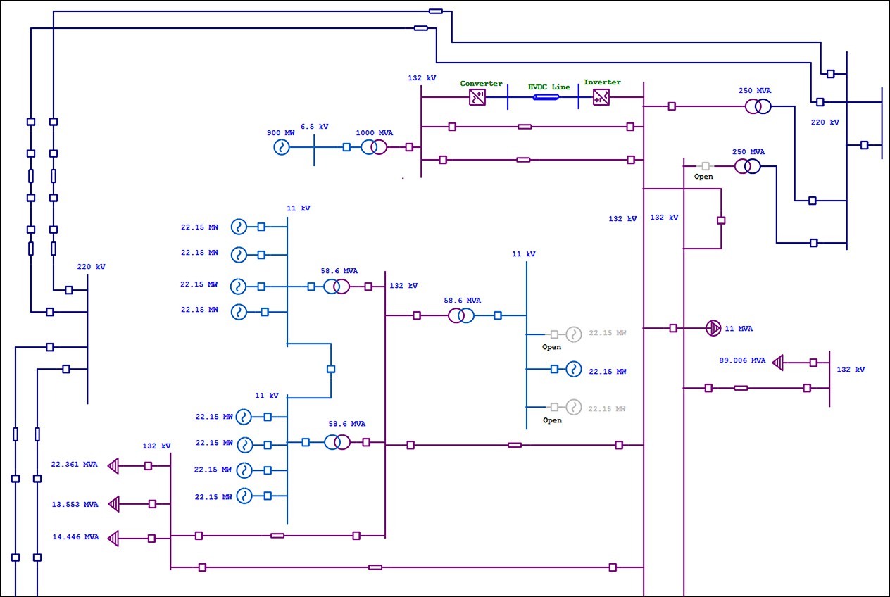
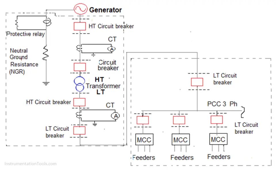
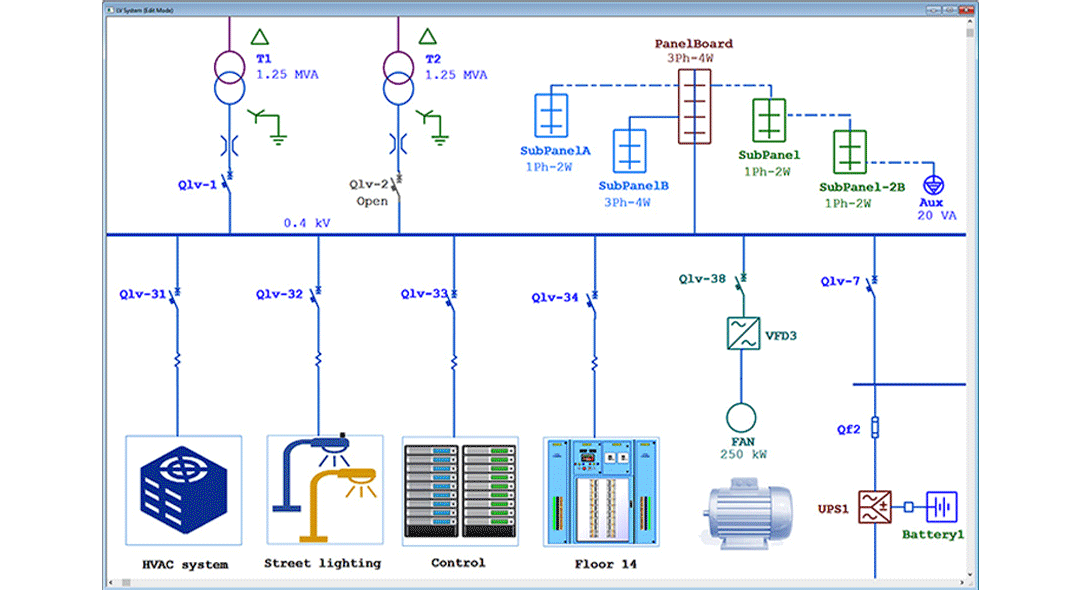
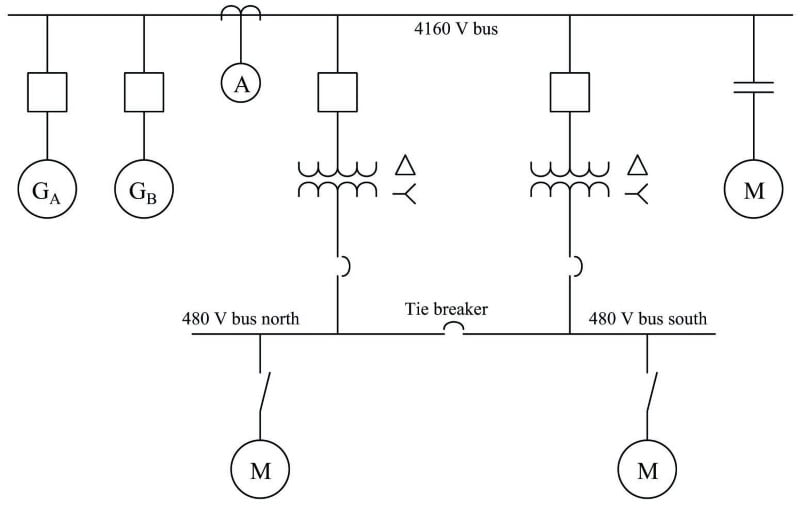
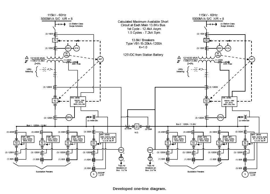
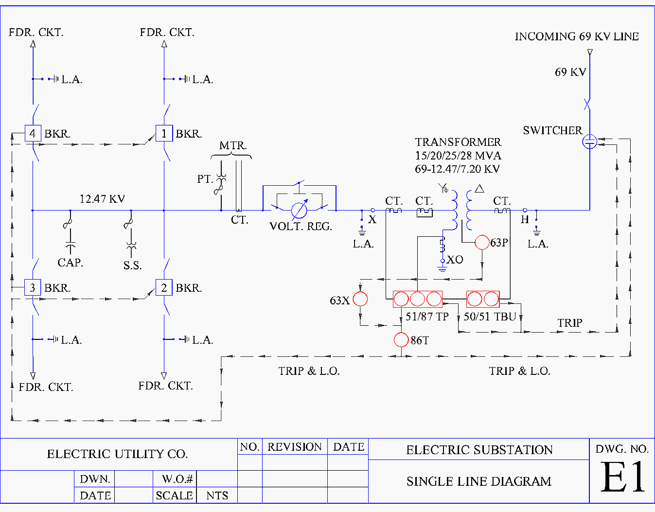
One Line Electrical Drawings - Web use the electrical engineering drawing type in visio professional or visio plan 2 to create electrical and electronic schematic diagrams. Hv/lv generation, power transmission & distribution of power. We will looking a normal set of plans o. We call this a shape connector. It is a simplified drawing of the whole system or a portion of the power system that shows the electrical placement of all major equipment. The diagram is commonly used in designing, operating, and maintaining electrical power systems. It will have one single line shown for bus (or cable) to represent all three phases. Start drawing lines by clicking on the line tool at the top of the smartpanel. Web by r jagan mohan rao. Web single line diagrams are used in common engineering practice as graphical representation of electrical switchboard or assembly containing more sections, i.e. Electrical power grids primarily consist of. A diagram which shows, by means of single lines and graphic symbols, the course of an electric circuit or system of circuits and the component devices or parts used therein. Web below is the csa z462 single line diagram definition: Web by the end of this video will completely understand the ideals of the. It is used by electricians, engineers, and technicians to understand the electrical components and connections within a system. Start drawing lines by clicking on the line tool at the top of the smartpanel. A diagram which shows, by means of single lines and graphic symbols, the course of an electric circuit or system of circuits and the component devices or. Web single line diagrams are used in common engineering practice as graphical representation of electrical switchboard or assembly containing more sections, i.e. It is the first step in preparing a critical response plan, allowing you to become thoroughly familiar with the electrical distribution system layout and design in your facility. It will have one single line shown for bus (or. Start drawing lines by clicking on the line tool at the top of the smartpanel. So easy, in fact, practically anyone can use it. On the file tab, select new, and then search for engineering templates. “a diagram which shows, by means of single lines and graphic symbols, the course of an electric circuit or system of circuits and the. It shows the flow of electricity through the system using a single line and standardized electrical symbols. We call this a shape connector. Select one of the following: Start drawing lines by clicking on the line tool at the top of the smartpanel. [1] [2] a single line in the diagram typically corresponds to more than one physical conductor: The diagram is commonly used in designing, operating, and maintaining electrical power systems. You circuit diagram will basically visualize circuits as lines and the added symbols will indicate where switches and fusers may go. We call this a shape connector. We will looking a normal set of plans o. Start drawing lines by clicking on the line tool at the. Web by r jagan mohan rao. Web single line diagrams are used in common engineering practice as graphical representation of electrical switchboard or assembly containing more sections, i.e. Web design a single line diagram in autocad. Simplification of low and/or high voltage distribution, to provide an “overview” of the installation. It is a simplified drawing of the whole system or. Web by the end of this video will completely understand the ideals of the one line diagram from a electrical perspective. As the name suggests, a single line is used to denote the multiple power lines such as in 3. The diagram is commonly used in designing, operating, and maintaining electrical power systems. Web design a single line diagram in. So easy, in fact, practically anyone can use it. It shows the flow of electricity through the system using a single line and standardized electrical symbols. You circuit diagram will basically visualize circuits as lines and the added symbols will indicate where switches and fusers may go. How is a single line diagram calculated? By default, you'll draw a segmented. Web by r jagan mohan rao. The diagram is commonly used in designing, operating, and maintaining electrical power systems. We will looking a normal set of plans o. “a diagram which shows, by means of single lines and graphic symbols, the course of an electric circuit or system of circuits and the component devices or parts used therein.” Web use. Hv/lv generation, power transmission & distribution of power. It is the first step in preparing a critical response plan, allowing you to become thoroughly familiar with the electrical distribution system layout and design in your facility. “a diagram which shows, by means of single lines and graphic symbols, the course of an electric circuit or system of circuits and the component devices or parts used therein.” As the name suggests, a single line is used to denote the multiple power lines such as in 3. A diagram which shows, by means of single lines and graphic symbols, the course of an electric circuit or system of circuits and the component devices or parts used therein. It is used by electricians, engineers, and technicians to understand the electrical components and connections within a system. Start drawing lines by clicking on the line tool at the top of the smartpanel. Web by r jagan mohan rao. The diagram is commonly used in designing, operating, and maintaining electrical power systems. It will have one single line shown for bus (or cable) to represent all three phases. Web we usually depict the electrical distribution system by a graphic representation called a single line diagram (sld). We call this a shape connector. A single line can show all or part of a system. Simplification of low and/or high voltage distribution, to provide an “overview” of the installation. Web design a single line diagram in autocad. It shows the flow of electricity through the system using a single line and standardized electrical symbols.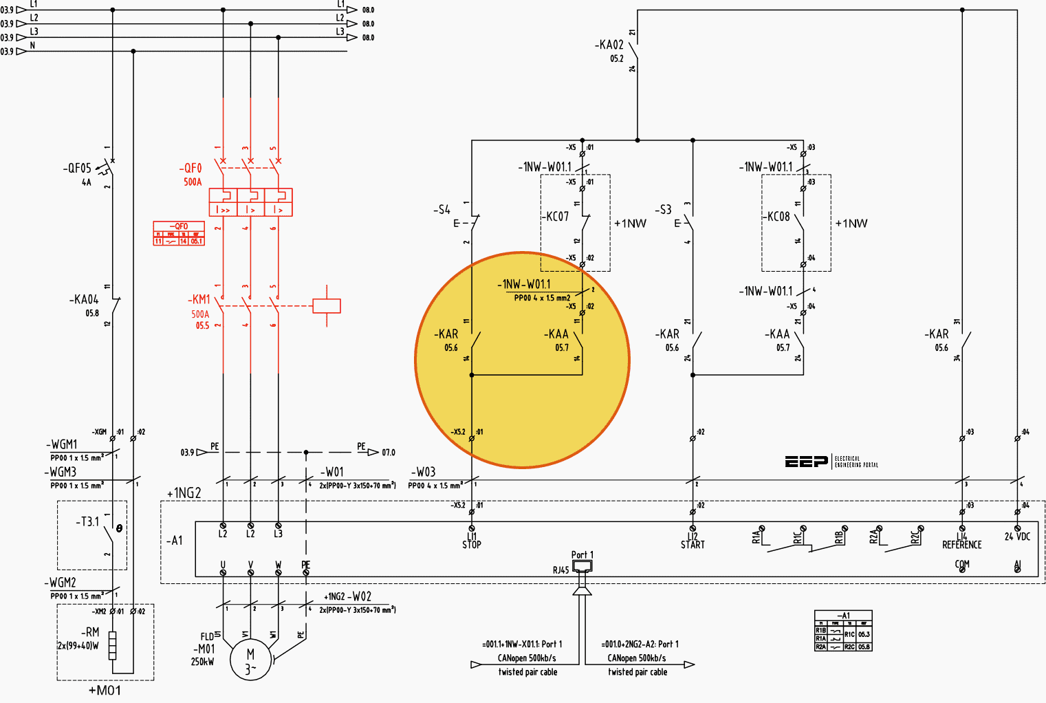
Learn to read and understand single line diagrams & wiring diagrams EEP
Electrical SingleLine Diagram Electrical OneLine Diagram ETAP
Electrical Single Line Diagram Template (DWG) — LINE DRAW CAD LAB

Simplified Electrical Oneline Diagram for the Forrestal Building
How to Read and Understand an Electrical Single Line Diagram?
Intelligent One Line Diagram Electrical SingleLine Diagram ETAP
Singleline Electrical Diagrams Electric Power Measurement and
Electrical Single Line Diagram Part Two Electrical Knowhow

Single Line Diagram of Power Plant Power Systems
Electrical Single Line Diagram
Electrical Power Grids Primarily Consist Of.
This Is A Bit Like A Block Diagram.
Select One Of The Following:
Web Below Is The Csa Z462 Single Line Diagram Definition:
Related Post: