Isometric Engineering Drawing
Isometric Engineering Drawing - It is an axonometric projection in which the three coordinate axes appear equally foreshortened and the angle between any two of them is 120 degrees. Web welcome to the 8th video in our engineering drawing series, where we simplify isometric drawing using the most straightforward and comprehensible approach. When drawn under these guidelines, the lines parallel to these three axes are at their true (scale) lengths. Isometric drawings are easy once you learn the basic techniques. One method is a “reductive” method which involves drawing a “bounding box” around what will ultimately become the final drawing and “cutting away” the unnecessary parts. Web home » engineering drawing » what is isometric projection? Web in engineering drawing, the 'isometric view / isometric projection' and respective 'orthographic projection' of machine components are very important practices. Engineering drawings use standardised language and symbols. To make an isometric drawing, start with an orthographic drawing or with the object itself. Web how to make an isometric drawing. Web how to make an isometric drawing. Web in engineering drawing, the 'isometric view / isometric projection' and respective 'orthographic projection' of machine components are very important practices. [isometric view, drawing and representation] last updated on: It is an axonometric projection in which the three coordinate axes appear equally foreshortened and the angle between any two of them is 120. Web an engineering drawing is a subcategory of technical drawings. Blue = center line of piece or opening; [isometric view, drawing and representation] last updated on: What is an isometric drawing? One method is a “reductive” method which involves drawing a “bounding box” around what will ultimately become the final drawing and “cutting away” the unnecessary parts. Web in an isometric drawing, the object’s vertical lines are drawn vertically, and the horizontal lines in the width and depth planes are shown at 30 degrees to the horizontal. Web welcome to the 8th video in our engineering drawing series, where we simplify isometric drawing using the most straightforward and comprehensible approach. Free mobile app24/7 tech supportpaperless solutionscancel anytime. In this tutorial, we'll guide you. The representation of the object in figure 2 is called an isometric drawing. This makes understanding the drawings simple with little to no personal interpretation possibilities. Web an engineering drawing is a subcategory of technical drawings. Web welcome back, engineering enthusiasts! Participants may also bring company drawings for interpretation during live case studies. One method is a “reductive” method which involves drawing a “bounding box” around what will ultimately become the final drawing and “cutting away” the unnecessary parts. Web how to make an isometric drawing. The isometric projection of an object on a vertical plane of projection by placing the. In this comprehensive tutorial, we delve into the art of creating flawless isometric views using orthographic projecti. April 26, 2021 by saif m. 195k views 1 year ago engineering drawing (english) in this video, i have explained how to draw an isometric view of an object from an orthographic view. The purpose is to convey all the information necessary for. Black = object line and hatching; This makes understanding the drawings simple with little to no personal interpretation possibilities. What is an isometric drawing? Web welcome to the 8th video in our engineering drawing series, where we simplify isometric drawing using the most straightforward and comprehensible approach. Magenta = phantom line or cutting plane line [isometric view, drawing and representation] last updated on: It is 2d drawings that represent. In this comprehensive tutorial, we delve into the art of creating flawless isometric views using orthographic projecti. Web welcome to the 8th video in our engineering drawing series, where we simplify isometric drawing using the most straightforward and comprehensible approach. Black = object line and hatching; Free mobile app24/7 tech supportpaperless solutionscancel anytime In this tutorial, we'll guide you. When drawn under these guidelines, the lines parallel to these three axes are at their true (scale) lengths. In an isometric drawing, the object's vertical lines are drawn vertically, and the horizontal lines in the width and depth planes are shown at 30 degrees to the horizontal.. The isometric projection of an object on a vertical plane of projection by placing the object in such a way that its three perpendicular edges make equal inclinations with the plane of. Shop best sellersfast shippingread ratings & reviewsshop our huge selection What is an isometric drawing? Towards drawing or interpreting the isometric views and orthographic projections, mental mapping of. Web welcome to the 8th video in our engineering drawing series, where we simplify isometric drawing using the most straightforward and comprehensible approach. Web in an isometric drawing, the object’s vertical lines are drawn vertically, and the horizontal lines in the width and depth planes are shown at 30 degrees to the horizontal. 195k views 1 year ago engineering drawing (english) in this video, i have explained how to draw an isometric view of an object from an orthographic view. Isometric drawings are easy once you learn the basic techniques. It is an axonometric projection in which the three coordinate axes appear equally foreshortened and the angle between any two of them is 120 degrees. Blue = center line of piece or opening; Towards drawing or interpreting the isometric views and orthographic projections, mental mapping of the various geometric shapes to their projections is very important. The purpose is to convey all the information necessary for manufacturing a product or a part. This makes understanding the drawings simple with little to no personal interpretation possibilities. In an isometric drawing, the object's vertical lines are drawn vertically, and the horizontal lines in the width and depth planes are shown at 30 degrees to the horizontal. April 26, 2021 by saif m. What is an isometric drawing? Engineering drawings use standardised language and symbols. [isometric view, drawing and representation] last updated on: These drawings are particularly useful for conveying a clear understanding of how different parts of a structure fit together. When drawn under these guidelines, the lines parallel to these three axes are at their true (scale) lengths.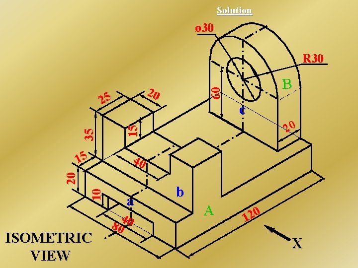
Engineering Drawing KITC Koraput

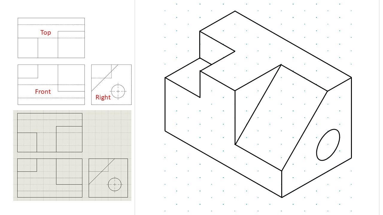
Engineering Drawing Tutorials/Isometric drawing with front and side
Isometric view drawing example 1 (easy). Links to practice files in

Engineering Drawing Isometric Projections Example 2 YouTube

Solidworks Tutorial/Advanced Isometric Drawing Isometric drawing

Drawings of ISOMETRIC PIPING DIAGRAMS retgas
Isometric Drawing at Explore collection of

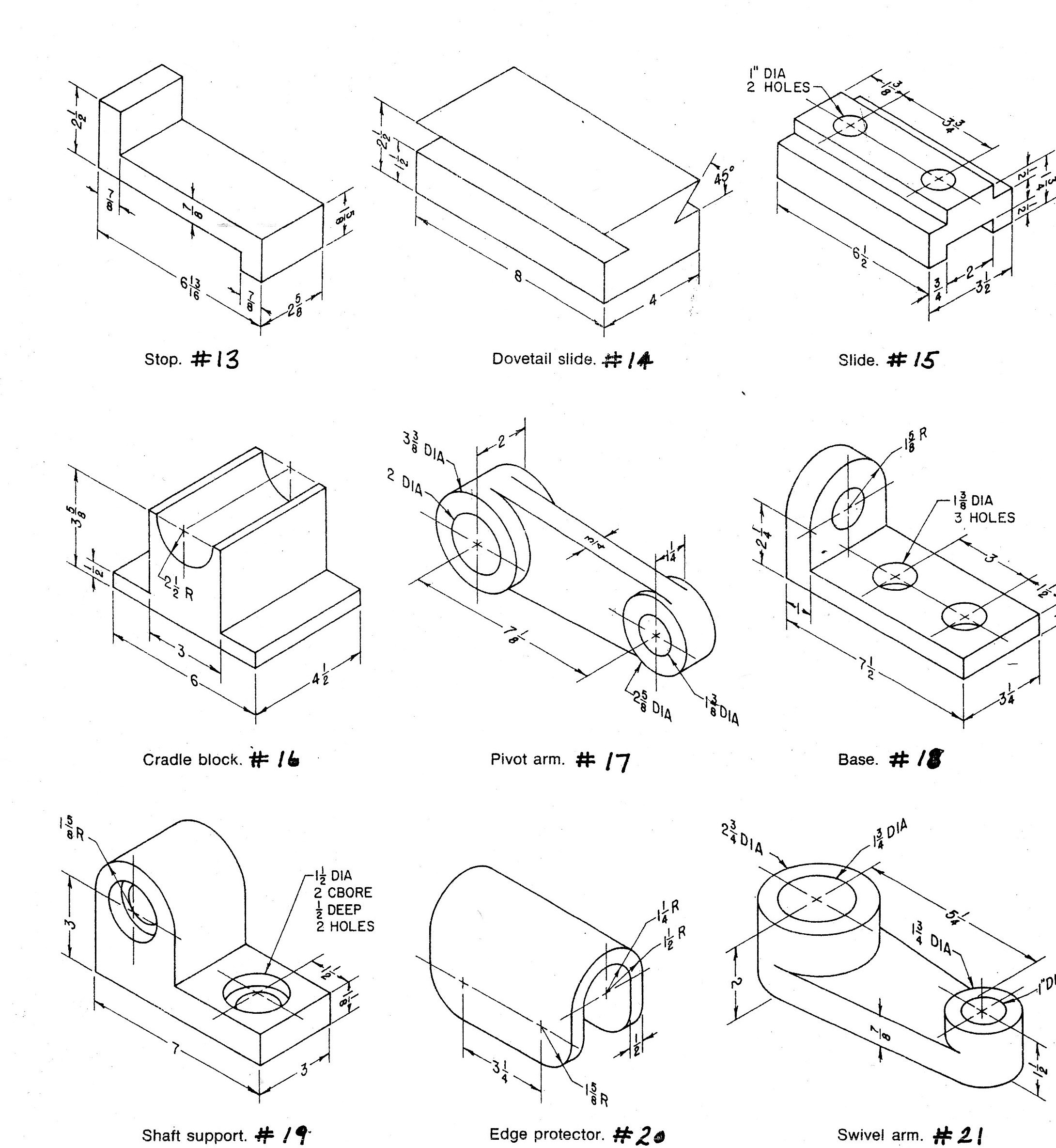
Isometric Drawing Basic Technical Drawing, 8th by Spencer, p. 138

ISOMETRIC TO ORTHOGRAPHIC PROJECTION SUM NO 1 TECHNICAL DRAWING
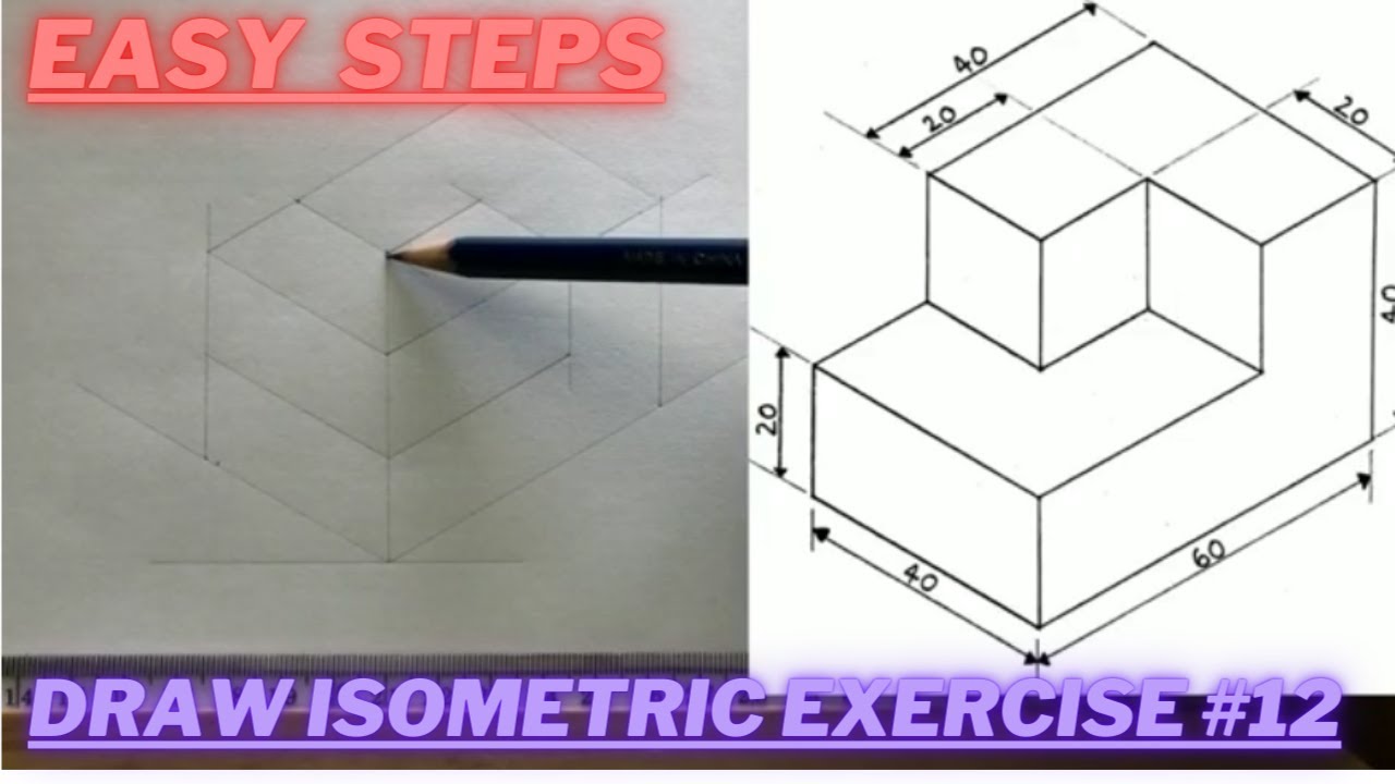
How to draw ISOMETRIC PROJECTIONS Technical Drawing Exercise 12
Web Welcome Back, Engineering Enthusiasts!
Web An Engineering Drawing Is A Subcategory Of Technical Drawings.
The Technique Is Intended To Combine The Illusion Of Depth, As In A Perspective Rendering, With The Undistorted Presentation Of The Object’s Principal Dimensions.
Web In Engineering Drawing, The 'Isometric View / Isometric Projection' And Respective 'Orthographic Projection' Of Machine Components Are Very Important Practices.
Related Post: