How To Read Pipe Drawings
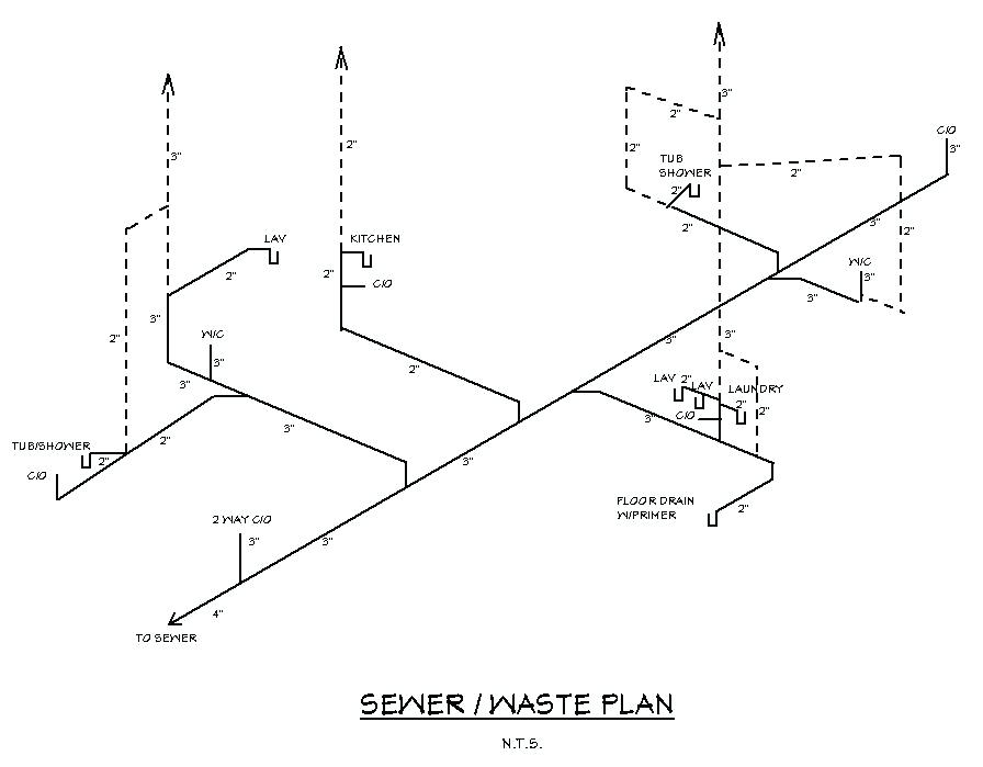
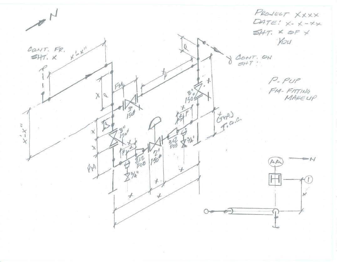
How To Read Pipe Drawings - So, not from the outside of a pipe or fitting. Start by reviewing the entire alignment drawing to get an overall sense of the pipeline route and any key features or obstacles that may be present. Familiarize yourself with the drawing: This video explain about piping isometric drawing details 1.how to read isometric drawings_basic. Piping and pipeline drawing symbols throw lights on the type of joint like buttweld, socket weld, or threaded. Reading a piping isometric drawing basic training. Piping fabrication work is based on isometric drawings. Pipe routing, length, and coordinates. Web pipe spool drawings consist of three sections: Web for reading any piping isometric drawing you must have to familiar with these 04 important things: Web a piping isometric drawing is a technical drawing that depicts a pipe spool or a complete pipeline using an isometric representation. 66k views 1 year ago tutorials for pipe fitters and fabricators. Web for reading any piping isometric drawing you must have to familiar with these 04 important things: Written by anup kumar dey in pipeline, piping design basics,. Spacing or centreline distance between one pipe to the other line. Piping isometric drawing consists of three sections. Web peter woolf et al. A piping plan drawing provides the following necessary information: Reading p&id is difficult for those who start their careers in oil &gas and similar chemical process industries. The full form of p&id is process and instrumentation diagram. 66k views 1 year ago tutorials for pipe fitters and fabricators. You need to know what p&id symbols mean and how each symbol is constructed using graphical elements and connecting lines. Web a piping isometric drawing is a technical drawing that depicts a pipe spool or a complete pipeline using. 254k views 2 years ago. Web pipe spool drawings consist of three sections: What is covered in this course. The book explains how to: Web how to read a piping isometric? Piping isometric drawing consists of three sections. So, not from the outside of a pipe or fitting. The full form of p&id is process and instrumentation diagram. Pythagoras theorem (for rolling movement of pipe) let’s first. The image below shows a orthographic view of a butt welded pipe with three sizes (a, b, c). 254k views 2 years ago. Reading p&id is difficult for those who start their careers in oil &gas and similar chemical process industries. Main graphic, bill of material, and title bar. Web piping technical trainer. Isometric drawing piping symbols serve as a ready reference for the type of fittings and components. Written by anup kumar dey in pipeline, piping design basics, piping interface, process. Dimensions and location of instruments. Web piping technical trainer. Reading p&id is difficult for those who start their careers in oil &gas and similar chemical process industries. So, not from the outside of a pipe or fitting. Web how to read piping isometrics using real plant drawings. Web piping technical trainer. Main graphic, bill of material, and title bar. Web peter woolf et al. The book explains how to: Web piping technical trainer. The image below shows a orthographic view of a butt welded pipe with three sizes (a, b, c). A piping plan drawing provides the following necessary information: Familiarize yourself with the drawing: 254k views 2 years ago. Piping isometric drawing consists of three sections. You need to know what p&id symbols mean and how each symbol is constructed using graphical elements and connecting lines. 3.5+ hours of high quality video lessons. Familiarize yourself with the drawing: Web how to read piping isometrics using real plant drawings. The image below shows a orthographic view of a butt welded pipe with three sizes (a, b, c). The book explains how to: Stephanus oscar, kaitlin harrington , suhendra lie. Web piping technical trainer. 2/5 in the series how to interpret piping and instrumentation diagrams. A piping plan drawing provides the following necessary information: Reading a piping isometric drawing basic training. Web peter woolf et al. Familiarize yourself with the drawing: A piping and instrumentation diagram, or p&id, shows the piping and related components of a physical process flow. You need to know what p&id symbols mean and how each symbol is constructed using graphical elements and connecting lines. This single line is the centerline of the pipe, and from that line, the dimensions measured. How to read iso drawings. Web how to read a piping isometric? Here’s a basic guide on how to read these essential engineering drawings: These drawings, also known as process and instrumentation diagrams, or process and control diagrams, are essential to many industrial operations.
How to read isometric drawing piping dadver
How to read piping isometric drawing plmservers

How to Read Basic Piping Isometric Drawings Piping Analysis YouTube
How to read piping isometric drawing plmservers

Piping Design Basics Piping Isometric Drawings Piping Isometrics

How to read piping Isometric drawing YouTube

How to read pipe drawing? Isometric explanation YouTube
How to read iso pipe drawings perlogistics

How to read isometric drawing piping dadver

How to read piping isometric drawing, Pipe fitter training, Watch the
We Are Concluding Our First Pipefitter Series Run With A Video On How To Draw Isometric Drawings.
Web Knowing The Piping Drawing Symbols Will Provide Various Information Like:
Type Of Pipe Supports Required In The Piping And Pipeline Systems.
Start By Reviewing The Entire Alignment Drawing To Get An Overall Sense Of The Pipeline Route And Any Key Features Or Obstacles That May Be Present.
Related Post: