Engineered Drawings
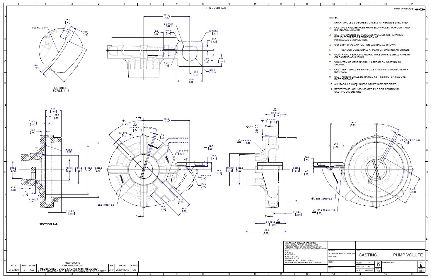
Engineered Drawings - Web an engineering drawing is a subcategory of technical drawings. This makes understanding the drawings simple with little to no personal interpretation possibilities. We will treat “sketching” and “drawing” as one. This is just an introduction. The video below covers the fundamentals, including the different types of views, first and third angle projection methods, dimensioning, tolerancing, best practices when creating drawings. It is more than simply a drawing, it is a graphical language that communicates ideas and information. “sketching” generally means freehand drawing. Web engineering drawings (aka blueprints, prints, drawings, mechanical drawings) are a rich and specific outline that shows all the information and requirements needed to manufacture an item or product. An engineering (or technical) drawing is a graphical representation of a part, assembly, system, or structure and it can be produced using freehand, mechanical tools, or computer methods. Web engineers, electricians, and contractors all use these drawings as deliverables and (often legally guarded) constructable documents when constructing or repairing objects and buildings. The engineering drawing rules are defined and embodied in the publications of standards organizations (for example, iso and asme ). It is more than simply a drawing, it is a graphical language that communicates ideas and information. Web engineering drawings (aka blueprints, prints, drawings, mechanical drawings) are a rich and specific outline that shows all the information and requirements needed. Web introduction to engineering drawing. These can be drafted by hand, or technical drawings can utilize cad software for. Web every phase of engineering design starting from concept illustration all the way to the manufacturing phase. Web engineering drawings are key tools that engineers use to communicate, but deciphering them isn’t always straightforward. Web an engineering drawing is a subcategory. The purpose is to convey all the information necessary for manufacturing a product or a part. Web an engineering drawing is a subcategory of technical drawings. Web engineers, electricians, and contractors all use these drawings as deliverables and (often legally guarded) constructable documents when constructing or repairing objects and buildings. 1.1 definition and overview of engineering drawing. 1.2 historical background. The engineering drawing rules are defined and embodied in the publications of standards organizations (for example, iso and asme ). Web an engineering drawing is a subcategory of technical drawings. “drawing” usually means using drawing instruments, from compasses to computers to bring precision to the drawings. Web the purpose of this guide is to give you the basics of engineering. The engineering drawing rules are defined and embodied in the publications of standards organizations (for example, iso and asme ). An engineering (or technical) drawing is a graphical representation of a part, assembly, system, or structure and it can be produced using freehand, mechanical tools, or computer methods. Web an engineering drawing is a type of technical drawing that is. 1.4 types of engineering drawing: The purpose is to convey all the information necessary for manufacturing a product or a part. The engineering drawing rules are defined and embodied in the publications of standards organizations (for example, iso and asme ). The video below covers the fundamentals, including the different types of views, first and third angle projection methods, dimensioning,. These can be drafted by hand, or technical drawings can utilize cad software for. Web an engineering drawing is a type of technical drawing that is used to convey information about an object. Web the purpose of this guide is to give you the basics of engineering sketching and drawing. Web engineering drawings are key tools that engineers use to. This makes understanding the drawings simple with little to no personal interpretation possibilities. The purpose is to convey all the information necessary for manufacturing a product or a part. “sketching” generally means freehand drawing. The engineering drawing rules are defined and embodied in the publications of standards organizations (for example, iso and asme ). 1m views 1 year ago. Web engineers, electricians, and contractors all use these drawings as deliverables and (often legally guarded) constructable documents when constructing or repairing objects and buildings. Web every phase of engineering design starting from concept illustration all the way to the manufacturing phase. 1.3 importance in various fields like mechanical engineering, civil engineering, etc. Usually, a number of drawings are necessary to. Web every phase of engineering design starting from concept illustration all the way to the manufacturing phase. “sketching” generally means freehand drawing. Web engineering drawings are key tools that engineers use to communicate, but deciphering them isn’t always straightforward. 1.1 definition and overview of engineering drawing. Web introduction to engineering drawing. Web an engineering drawing is a subcategory of technical drawings. Usually, a number of drawings are necessary to completely specify even a simple component. Engineering drawings use standardised language and symbols. This is just an introduction. These can be drafted by hand, or technical drawings can utilize cad software for. A common use is to specify the geometry necessary for the construction of a component and is called a detail drawing. The engineering drawing rules are defined and embodied in the publications of standards organizations (for example, iso and asme ). Web engineering drawings are key tools that engineers use to communicate, but deciphering them isn’t always straightforward. “drawing” usually means using drawing instruments, from compasses to computers to bring precision to the drawings. This makes understanding the drawings simple with little to no personal interpretation possibilities. The video below covers the fundamentals, including the different types of views, first and third angle projection methods, dimensioning, tolerancing, best practices when creating drawings. We will treat “sketching” and “drawing” as one. Web engineering drawings (aka blueprints, prints, drawings, mechanical drawings) are a rich and specific outline that shows all the information and requirements needed to manufacture an item or product. The purpose is to convey all the information necessary for manufacturing a product or a part. “sketching” generally means freehand drawing. Web introduction to engineering drawing.
Engineering Drawing at GetDrawings Free download
Engineering Drawing at GetDrawings Free download
Mechanical Engineering Drawing at GetDrawings Free download

Mechanical Engineer Drawing at GetDrawings Free download
Engineering Drawings Justin R. Palmer
Engineering Drawing A Science or Art RRCE

Mechanical Engineering Drawing and Design, Everything You Need To Know
Engineering Drawing Symbols And Their Meanings Pdf at GetDrawings

how to read civil engineering drawings Engineering Feed
Engineering Drawing YouTube
1M Views 1 Year Ago.
We Can Observe Engineering Drawings As A Unified Language That Engineers Use To Communicate Independently Of Each Other’s Spoken Or Written Language.
It Is More Than Simply A Drawing, It Is A Graphical Language That Communicates Ideas And Information.
1.2 Historical Background And Evolution.
Related Post: