Drawing Symbols Meaning
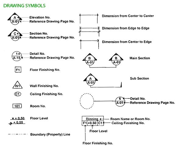
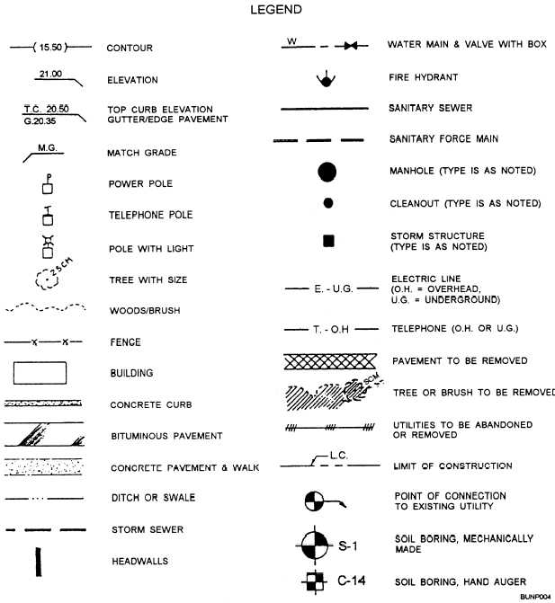
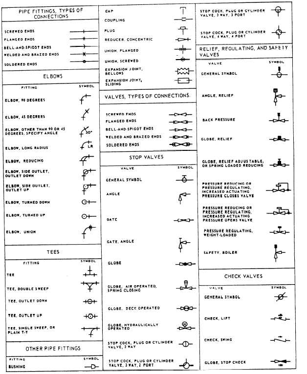
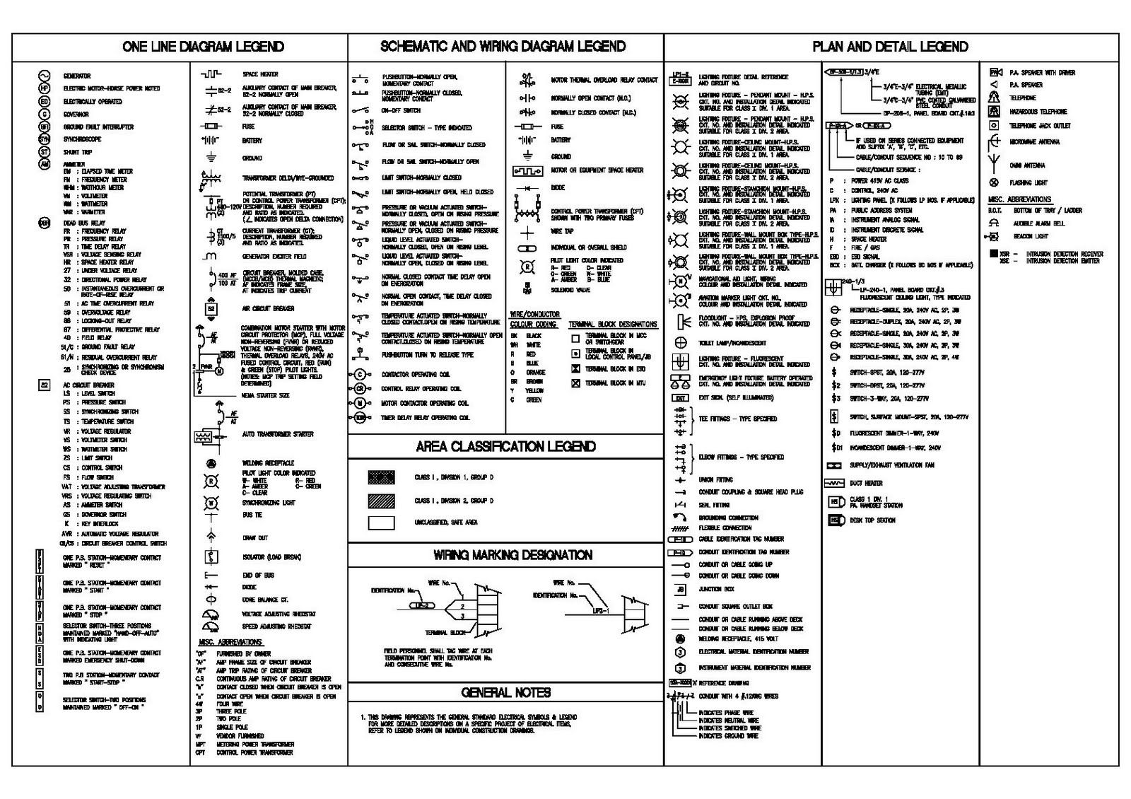
Drawing Symbols Meaning - Here are more commonly used engineering drawing symbols and design elements as below. This list includes abbreviations common to the vocabulary of people who work with engineering drawings in the manufacture and inspection of parts and assemblies. Web symbols for features. Web how to read an engineering drawing symbol. The distance from the center of a circle to the edge. The distance all the way across a circle. Web a convenient guide for geometric dimensioning and tolerancing (gd&t) symbols at your fingertips. Gd&t controls variations of size, form, orientation, location and runout individually or in combination. Engineering drawings are technical diagrams and representations meant to define parameters and other plans for something that is to be engineered. Web for example, engineering symbols are used in technical drawings to convey the specific geometry and other details about pieces of equipment or components. Need to know for dispelling uncertainty in drawings. These symbols and abbreviations are standardized by the american national standards institute (asmi) and the american society of mechanical engineers (asme) in the us. Web the table shows dimensioning symbols found on drawings. This guide to 114 different cad symbols acts as a handy reference. Web for example, engineering symbols are used. Web some common engineering drawing symbols include geometric symbols (circle, square, triangle), symbols for surface finish (roughness, smoothness), symbols for welding (fillet weld, plug weld), symbols for electrical circuits (resistor, capacitor), and symbols for mechanical components (gears, bearings). Web gd&t drawings and symbols. Web how to read an engineering drawing symbol. It is more than simply a drawing, it is. Most symbols have been in y14.5 since at least 1994. Need to know for dispelling uncertainty in drawings. The symbols and abbreviations represent various components, processes, and measurements used in engineering design. Web construction drawing symbols serve as the common language that architects, engineers and builders rely on to ensure every aspect of the project aligns with the original vision.. Web engineering drawing abbreviations are a set of standardized symbols and abbreviations used on engineering drawings to represent common terms and phrases. This document describes and illustrates common dimensioning, gd&t, architectural, piping, and electrical symbols. Need to know for dispelling uncertainty in drawings. Web some common engineering drawing symbols include geometric symbols (circle, square, triangle), symbols for surface finish (roughness,. Gd&t controls variations of size, form, orientation, location and runout individually or in combination. These standards define the symbols, rules and best practices for using and interpreting gd&t. Learn the ins and outs of engineering drawing standards, such as iso and ansi, which govern the symbols, abbreviations, and notations used in. Click on the links below to learn more about. Geometric dimensioning and tolerancing (gd&t) consists of a set of symbols and rules for applying them that communicates the requirements of an engineering blueprint. Most symbols have been in y14.5 since at least 1994. Web may 1, 2022 by brandon fowler. These symbols and abbreviations are standardized by the american national standards institute (asmi) and the american society of mechanical. The distance from the center of a circle to the edge. However, symbols can be meaningful only if they are created according to the relevant standards or conventions. Web basic types of symbols used in engineering drawings are countersink, counterbore, spotface, depth, radius, and diameter. The distance all the way across a circle. Most symbols have been in y14.5 since. This list includes abbreviations common to the vocabulary of people who work with engineering drawings in the manufacture and inspection of parts and assemblies. This guide to 114 different cad symbols acts as a handy reference. This document describes and illustrates common dimensioning, gd&t, architectural, piping, and electrical symbols. To limit errors caused by personal interpretation, engineering drawings and diagrams. Most symbols have been in y14.5 since at least 1994. They represent components, elements, details, characteristics, actions, features, and conditions important for a defined technical product or system. Gd&t controls variations of size, form, orientation, location and runout individually or in combination. These symbols and abbreviations are standardized by the american national standards institute (asmi) and the american society of. This article aims to clarify the role and importance of construction drawing symbols in the construction industry. This guide to 114 different cad symbols acts as a handy reference. Web various symbols and abbreviations in engineering drawings give you information about the dimensions, design, and materials used. Geometric tolerances are specified using symbols on a drawing. Web the table shows. Web basic types of symbols used in engineering drawings are countersink, counterbore, spotface, depth, radius, and diameter. Gd&t controls variations of size, form, orientation, location and runout individually or in combination. Web drafting symbols symbols provide a “common language” for drafters all over the world. Web may 1, 2022 by brandon fowler. Geometric dimensioning and tolerancing (gd&t) consists of a set of symbols and rules for applying them that communicates the requirements of an engineering blueprint. Web symbols in mechanical drawings are graphical elements accepted by standards and codes. To limit errors caused by personal interpretation, engineering drawings and diagrams are governed by standardized language and symbols. Currently, we have 16 symbols for geometric tolerances, which are categorized according to the tolerance they specify. Web how to read an engineering drawing symbol. This document describes and illustrates common dimensioning, gd&t, architectural, piping, and electrical symbols. Need to know for dispelling uncertainty in drawings. This list includes abbreviations common to the vocabulary of people who work with engineering drawings in the manufacture and inspection of parts and assemblies. This symbol gets used with other symbols as well such as counterbores, countersinks, and true position callouts. Web some common engineering drawing symbols include geometric symbols (circle, square, triangle), symbols for surface finish (roughness, smoothness), symbols for welding (fillet weld, plug weld), symbols for electrical circuits (resistor, capacitor), and symbols for mechanical components (gears, bearings). It is more than simply a drawing, it is a graphical language that communicates ideas and information. Learn the ins and outs of engineering drawing standards, such as iso and ansi, which govern the symbols, abbreviations, and notations used in.
Mechanical Drawing Symbols Mathematics Symbols Process Flow Diagram
Civil Engineering Drawing Symbols And Their Meanings at PaintingValley

Civil Engineering Drawing Symbols And Their Meanings at PaintingValley

Engineering Drawing Symbols List Chart Explain Mechanical Drawing
Civil Engineering Drawing Symbols And Their Meanings at PaintingValley
Engineering Drawing Symbols And Their Meanings Pdf at PaintingValley

Types of Engineering Drawing Symbols and Uses इंजीनियरिंग ड्राइंग के

Engineering Drawing Symbols And Their Meanings Pdf at PaintingValley

Engineering Drawing Symbols And Their Meanings Pdf at PaintingValley
Engineering Drawing Symbols And Their Meanings Pdf at PaintingValley
Web The Table Shows Dimensioning Symbols Found On Drawings.
The Following Is A Short List Of Symbols That Normally Appear On A Technical Drawing And Need Understanding.
Web 5 Types Of Gd&T Symbols.
Here Are More Commonly Used Engineering Drawing Symbols And Design Elements As Below.
Related Post: