Draw The Shear And Moment Diagrams For The Loaded Beam
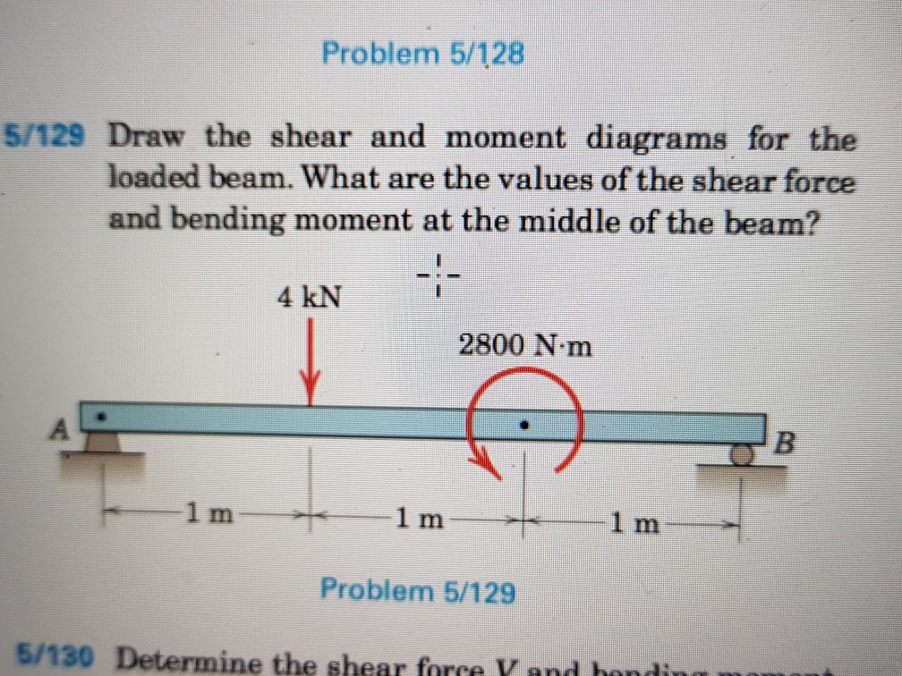
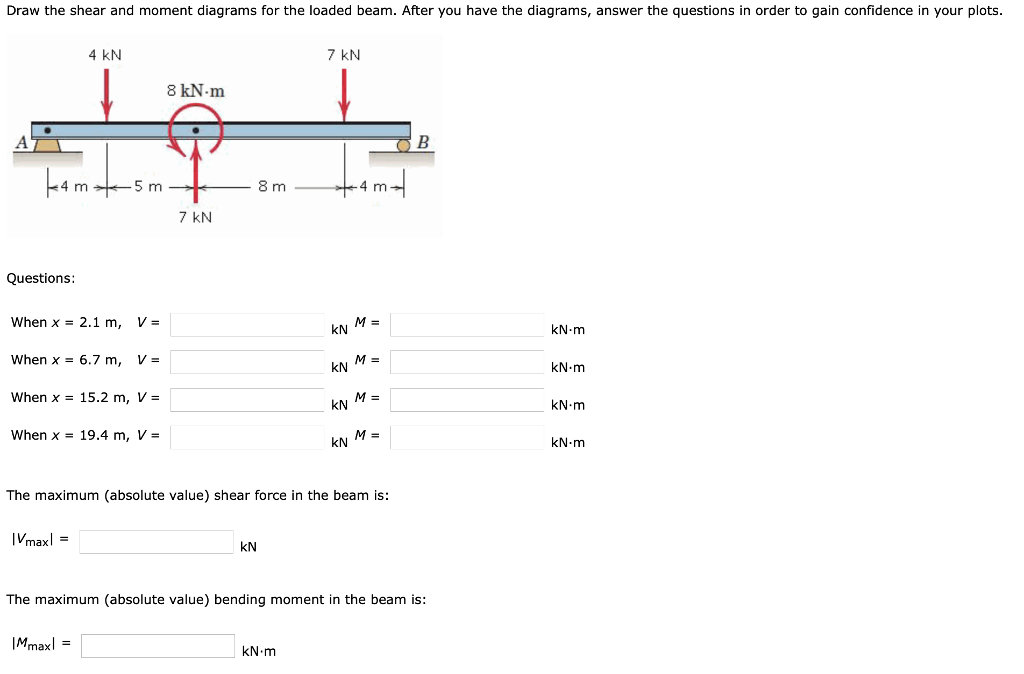
Draw The Shear And Moment Diagrams For The Loaded Beam - What are the values of the shear force and bending moment at the middle of the beam? But in order to find the shear and moment at every point in the object you will need a more powerful approach. Web the first step in calculating these quantities and their spatial variation consists of constructing shear and bending moment diagrams, \(v(x)\) and \(m(x)\), which are the internal shearing forces and bending moments induced in. Web draw the shear and moment diagrams for the loaded beam. Web figures 1 through 32 provide a series of shear and moment diagrams with accompanying formulas for design of beams under various static loading conditions. Let reaction at supports a and b be r a and r b respectively σ f y = 0. 11k views 2 years ago chapter. 5 kn 7 kn 9 kn/m 6 kn/m b kamt 7 m 10 m 6 m questions: Draw out a free body diagram of the body horizontally. After you have the diagrams, answer the questions in order to gain confidence in your plots. After you have the diagrams, answer the questions in order to gain confidence in your plots. After you have the diagrams, answer the questions as a check on your work. This is an example problem that will show you how to graphically draw a shear and moment diagram for a. The distributed load is the slope of the shear diagram. Web beam guru.com is a online calculator that generates bending moment diagrams (bmd) and shear force diagrams (sfd), axial force diagrams (afd) for any statically determinate (most simply supported and cantilever beams) and statically indeterminate beams, frames and trusses. State the value of the bending moment at midbeam. Suppose that we have a simply supported beam upon which there is. But in order to find the shear and moment at every point in the object you will need a more powerful approach. 1 kn 3 kn 7 kn.m k4m +5m 9m — *4m/ 2 kn questions: Web the previous section presented a method to find the shear and bending moment at a single point, which is useful; Draw out a. View the full answer step 2. This can be done by creating a shear and bending moment diagram. The shear force and bending moment diagrams are convenient visual references to the internal forces in a beam; The distributed load is the slope of the shear diagram and each point load represents a jump in the shear diagram. In each problem,. After you have the diagrams, answer the questions as a check on your work. Suppose that we have a simply supported beam upon which there is an applied load w(x) w ( x) which is distributed on the beam by some function of position, x, x, as shown in figure 8.6.1. This is an example problem that will show you. We go through breaking a beam into segments, and then we learn about the relationships between shear force. What are the values of the shear force and bending moment at the middle of the beam? Web chapter 5, problem 5/115 go tutorial draw the shear and moment diagrams for the loaded beam. Web below is a simple example of what. Download a customised selection of the above results in a formatted pdf report. Web beam guru.com is a online calculator that generates bending moment diagrams (bmd) and shear force diagrams (sfd), axial force diagrams (afd) for any statically determinate (most simply supported and cantilever beams) and statically indeterminate beams, frames and trusses. This can be done by creating a shear. View the full answer step 2. Web by plotting these expressions to scale, obtain the shear force and bending moment diagrams for the beam. Colorado state university via engineeringstatics. This can be done by creating a shear and bending moment diagram. We go through breaking a beam into segments, and then we learn about the relationships between shear force. There are 2 steps to solve this one. The shear force and bending moment diagrams are convenient visual references to the internal forces in a beam; ∑ m a = 0. But in order to find the shear and moment at every point in the object you will need a more powerful approach. Colorado state university via engineeringstatics. Web draw the shear and moment diagrams for the loaded beam. Let reaction at supports a and b be r a and r b respectively σ f y = 0. Web draw the shear and moment diagrams for the loaded cantilever beam. View the full answer step 2. But in order to find the shear and moment at every point. Relation between loading, shear and moment. What are the values of the shear force and bending moment at the middle of the beam? Please show all your working. Web shear force and bending moment diagrams are analytical tools used in conjunction with structural analysis to help perform structural design by determining the value of shear forces and bending moments at a given point of a structural element such as a beam. Web below is a simple example of what shear and moment diagrams look like, afterwards, the relation between the load on the beam and the diagrams will be discussed. 100% (1 rating) step 1. Web by plotting these expressions to scale, obtain the shear force and bending moment diagrams for the beam. Web figures 1 through 32 provide a series of shear and moment diagrams with accompanying formulas for design of beams under various static loading conditions. • loadings that are opposite to these are considered negative. ∑ m a = 0. Web write shear and moment equations for the beams in the following problems. There are 2 steps to solve this one. There are 2 steps to solve this one. 1 kn 3 kn 7 kn.m k4m +5m 9m — *4m/ 2 kn questions: But in order to find the shear and moment at every point in the object you will need a more powerful approach. When x = 1.3 m, v = kn m= kn.m when x = 6.9 m, v = m = kn kn.m when x = 16.6 m, v = kn m= kn.m when x =.
Solved Draw the shear and moment diagrams for the beam

Draw the shear and moment diagrams for the beam.
[Solved] Draw the shear and moment diagram of the loaded beam shown in
Solved Draw the shear and moment diagrams for the loaded

Learn How To Draw Shear Force And Bending Moment Diagrams Engineering

Solved Draw the shear and moment diagrams for the beam.
Solved Draw the shear and moment diagrams for the loaded

Solved Draw the shear and moment diagrams for the beam, and

Drawing Shear and Moment Diagrams for Beam YouTube
Solved Problem 5/128 5/129 Draw the shear and moment
R A + R B = 6 × 6 + 31 + 1 2 × 9 × 13 = 125.5 K N.
171K Views 5 Years Ago Rc Beam Design.
Web Sign Convention In Beam • The Positive Directions Are As Follows:
11K Views 2 Years Ago Chapter.
Related Post: