Diameter Symbol In Engineering Drawing
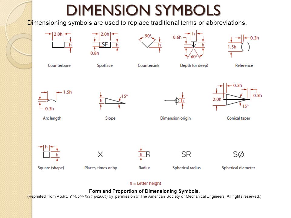
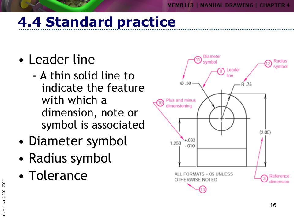
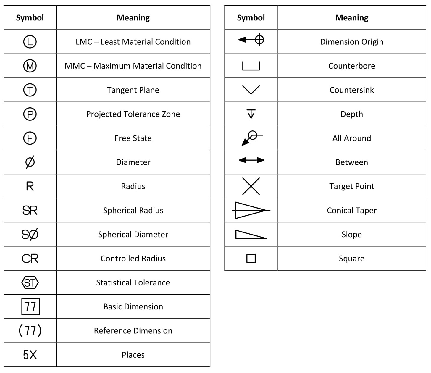
Diameter Symbol In Engineering Drawing - I’m pretty sure it’s something to do with the fitting, possibly specifying to use the minimum circumscribed or maximum inscribed circle to tolerance the diameter but i can’t remember. It should be used anywhere there is a diameter on the drawing,abd when a tolerence zone is cylindrical. The spherical diameter symbol indicates that the feature being dimensioned is spherical, rather than circular. Web a diameter symbol (⌀) signifies a diametric zone (cylindrical tolerance zone). Web engineering drawing abbreviations and symbols are used to communicate and detail the characteristics of an engineering drawing. Web it establishes symbols, rules, definitions, requirements, defaults, and recommended practices for stating and interpreting gd&t and related requirements for use on engineering drawings, models defined in digital data files, and in related documents. The symbol used is the greek letter phi. For example, a 20 diameter hole that goes straight through the component would be represented as “ø20 through”. How are simple holes shown on engineering drawings? Diameter symbol replaces the word diameter. The radius symbol used is the capital letter r. Web a diameter symbol is used on the diameter dimension. The symbol used is the greek letter phi ø. Why abbreviations and symbols are needed for engineering drawing? Web what does an e in a circle after a diameter mean? The radius symbol represents half the diameter of a circle or cylindrical feature. However, symbols can be meaningful only if they are created according to the. The second symbol in the 2nd block gives the value of the tolerance zone in mm. Web engineering drawing abbreviations and symbols are used to communicate and detail the characteristics of an engineering drawing.. How to read symbols in an engineering drawing? When dimensioning a part with multiple concentric cylindrical features, you should stagger the dimension numbers so that they are easier to distinguish. Web a diameter symbol (⌀) signifies a diametric zone (cylindrical tolerance zone). Modified 6 years, 6 months ago. In the quiz that completes the activity, they associate these symbols with. Web various symbols and abbreviations in engineering drawings give you information about the dimensions, design, and materials used. How are simple holes shown on engineering drawings? This list includes abbreviations common to the vocabulary of people who work with engineering drawings in the manufacture and inspection of parts and assemblies. Web diameter symbol (⌀): Radius symbol (r or ⌀ with. Web basic types of symbols used in engineering drawings are countersink, counterbore, spotface, depth, radius, and diameter. You can also check out the gd&t symbols and terms on our site. The radius symbol represents half the diameter of a circle or cylindrical feature. To specify a spherical zone, the symbol is the letter ‘s’ followed by the diameter symbol (⌀).. Simple holes are shown on engineering drawings by stating the diameter and the depth of the hole. Work with runsom for your cnc programming projects. Web diameter symbol — a symbol indicating that the dimension shows the diameter of a circle. Common engineering drawing abbreviations used in cnc machining. By kelly curran glenn sokolowski. When dimensioning a part with multiple concentric cylindrical features, you should stagger the dimension numbers so that they are easier to distinguish. ‘sø’ is used to represent the diameter of a spherical surface. This symbol is used to denote the diameter of a circle or cylindrical feature. Circles on a drawing are dimensioned with a diameter. These symbols and abbreviations. For example, a 20 diameter hole that goes straight through the component would be represented as “ø20 through”. A convenient guide for geometric dimensioning and tolerancing (gd&t) symbols at your fingertips. In the quiz that completes the activity, they associate these symbols with machining applications. Web the spherical diameter symbol is a variant of the diameter symbol, with the letter. Diameter symbol replaces the word diameter. The radius symbol represents half the diameter of a circle or cylindrical feature. Web a diameter symbol is used on the diameter dimension. Indicates a circular feature when used on the field of a drawing or indicates that tolerance is diametrial when used in a feature control frame. Asked 6 years, 6 months ago. Click on the links below to learn more about each gd&t symbol or concept, and be sure to download the free wall chart for a quick reference when at your desk or on the shop floor. Web diameter symbol (⌀): Tolerance — the amount that a particular dimension may vary. For example, is it either ø4.00 or 4.00 od but. Web various symbols and abbreviations in engineering drawings give you information about the dimensions, design, and materials used. Diameter symbol replaces the word diameter. You can also check out the gd&t symbols and terms on our site. Web various symbols and abbreviations in engineering drawings give you information about the dimensions, design, and materials used. Web the symbol used for a hole is the diameter ‘ø’ symbol. Web what does an e in a circle after a diameter mean? By kelly curran glenn sokolowski. Web gd&t symbols | gd&t basics. Tolerance — the amount that a particular dimension may vary. It should be used anywhere there is a diameter on the drawing,abd when a tolerence zone is cylindrical. Common engineering drawing abbreviations used in cnc machining. Web a diameter symbol (⌀) signifies a diametric zone (cylindrical tolerance zone). Here are more commonly used engineering drawing symbols and design elements as below. Click on the links below to learn more about each gd&t symbol or concept, and be sure to download the free wall chart for a quick reference when at your desk or on the shop floor. The radius symbol used is the capital letter r. Web basic types of symbols used in engineering drawings are countersink, counterbore, spotface, depth, radius, and diameter.
GD&T 101 An Introduction to Geometric Dimensioning and Tolerancing
Design Tech Academy (3) GD&T Symbols Diameter, Radius, Controlled

Technical Drawing Symbols And Their Meanings Design Talk

Lecture Notes Engineering Drawing Part 4
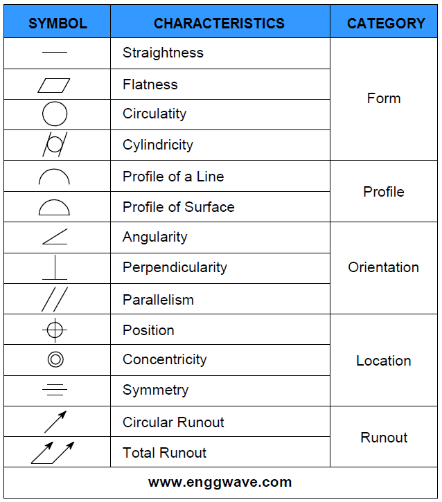
GD&T Symbols GD&T Terms Geometric Dimensioning and »

HOW TO DRAW A DIAMETER SYMBOL IN AUTOCAD. YouTube
Drafting And Dimensioning Symbols vrogue.co
Diameter Symbol OER
Dimension Symbols Of Drawing at GetDrawings Free download
What Are Geometric Dimensioning And Tolerancing Gd T Symbols Vrogue
These Symbols And Abbreviations Are Standardized By The American National Standards Institute (Asmi) And The American Society Of Mechanical Engineers (Asme) In The Us.
When Dimensioning A Part With Multiple Concentric Cylindrical Features, You Should Stagger The Dimension Numbers So That They Are Easier To Distinguish.
Radius Symbol — A Symbol Indicating That The Dimension Shows The Radius Of A Circle.
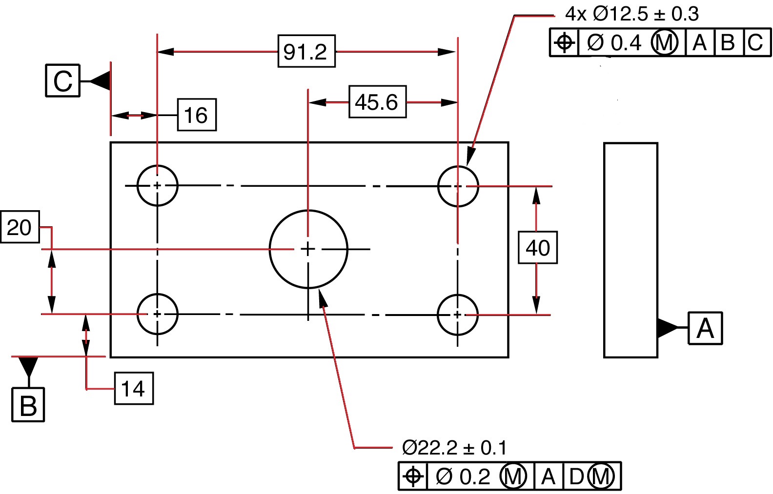
Web A Diameter Dimension Is Represented On A Drawing With The ‘Ø’ Symbol Preceding The Value As Shown In The Below Figure.
Related Post: