Break Lines In Engineering Drawing
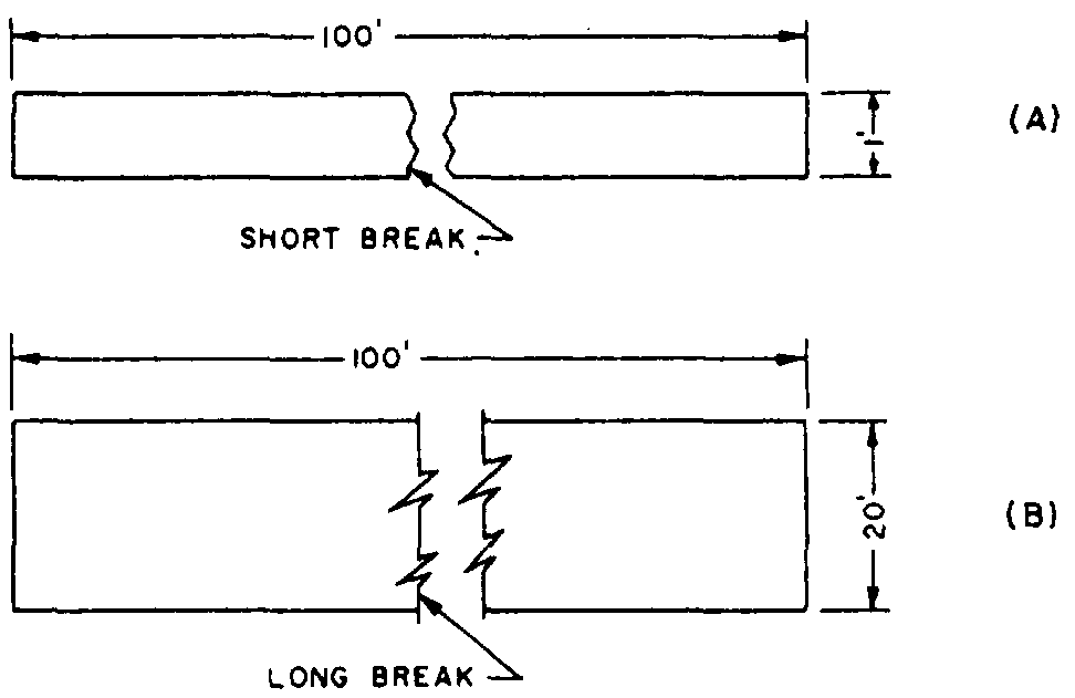
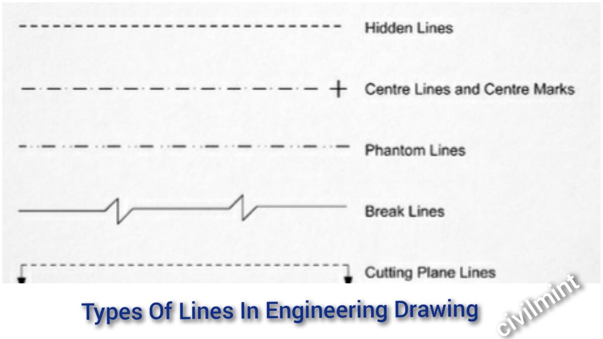
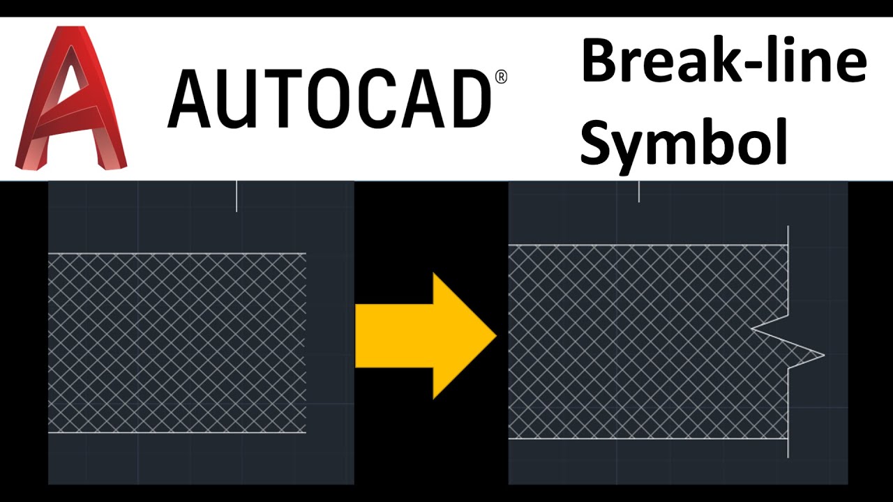
Break Lines In Engineering Drawing - As the name suggest, they are visible in an engineering drawing. Short break lines and long break lines. An engineering drawing is a subcategory of technical drawings. This tool is included with the drawing break lines extension. Web engineering drawings (aka blueprints, prints, drawings, mechanical drawings) are a rich and specific outline that shows all the information and requirements needed to manufacture an item or product. Clear up your drawings in solidworks with break lines. These are the same lines that you used to lay out your drafting sheet. On the end opposite the arrow, the leader line will have a short, horizontal shoulder. Drawings can range from very simple, with just a few dimensions, to extremely complex, with multiple views and sheets and too many dimensions to count. Web break lines are used to show where an object is broken to save drawing space or reveal interior features. Drawings can range from very simple, with just a few dimensions, to extremely complex, with multiple views and sheets and too many dimensions to count. Standardized line types were developed for use in the industry. Usually the first lines that you will use on a drawing are construction lines. Web in an isometric drawing, the object’s vertical lines are drawn. Thick or thin dashed line. Standardized line types were developed for use in the industry. Three types of break lines with different line weights: Short and long break lines are used for flat surfaces. They are dark and thick lines of any engineering design drawing. Break lines are used to shorten the size of a view for an exceptionally long part. Drawings can range from very simple, with just a few dimensions, to extremely complex, with multiple views and sheets and too many dimensions to count. Web there are 12 types of lines usually used in engineering drawing. Dimension and extension lines are. There are. Visible lines are dark and thick. They are used to remove, or ‘break out” part of a drawing for clarity, and also to shorten objects which have the same shape throughout their length and may be too long to place on the drawing. These lines are drawn to represent hidden or invisible edges of the objects. Web the continuous thin. By kelly curran glenn sokolowski. Web the continuous thin zigzag line shows a break line. When drawn under these guidelines, the lines parallel to these three axes are at their true (scale) lengths. A long, ruled thin line with zigzags. As the name suggest, they are visible in an engineering drawing. Short break lines and long break lines. Web 18.06.2020 by andreas velling. Drawings can range from very simple, with just a few dimensions, to extremely complex, with multiple views and sheets and too many dimensions to count. The dashed line is used to indicate. Why not just use a 3d model? This tool is included with the drawing break lines extension. By kelly curran glenn sokolowski. Web engineering drawings (aka blueprints, prints, drawings, mechanical drawings) are a rich and specific outline that shows all the information and requirements needed to manufacture an item or product. i have described each type of line briefly. Web there are three kinds of break lines. The two variations of break lines common to blueprints are the long break line and the short break line (figure 11). These lines are drawn to represent hidden or invisible edges of the objects. i have described each type of line briefly. In this highly interactive object, learners associate basic line types and terms with engineering drawing geometry. Curved lines. Visible lines are dark and thick. If yours fall into the first category, you might not have to do too much to display everything. Dimension and extension lines are. Web the continuous thin zigzag line shows a break line. Hidden lines are 0.3 mm thin dashed line. Web break lines are used to show where an object is broken to save drawing space or reveal interior features. Rectangular break line adds a rectangular break line to a drawing when two points are picked in a drawing view. i have described each type of line briefly. Web there are 12 types of lines usually used in engineering drawing.. Curved lines (arcs, circles, and ellipses) cutting plane lines. Each line type should exhibit a certain thickness on a finished drawing, known as line weight. Usually the first lines that you will use on a drawing are construction lines. Web line characteristics, such as widths, breaks in the line, and zigzags, all have definite meanings. There are two types of break lines: A freehand thick line, and. i have described each type of line briefly. Hidden lines are 0.3 mm thin dashed line. The dashed line is used to indicate. These are the same lines that you used to lay out your drafting sheet. A long, ruled thin line with zigzags. These types of lines also known as object lines. By kelly curran glenn sokolowski. It is more than simply a drawing, it is a graphical language that communicates ideas and information. Thick or thin dashed line. Web there are 12 types of lines usually used in engineering drawing.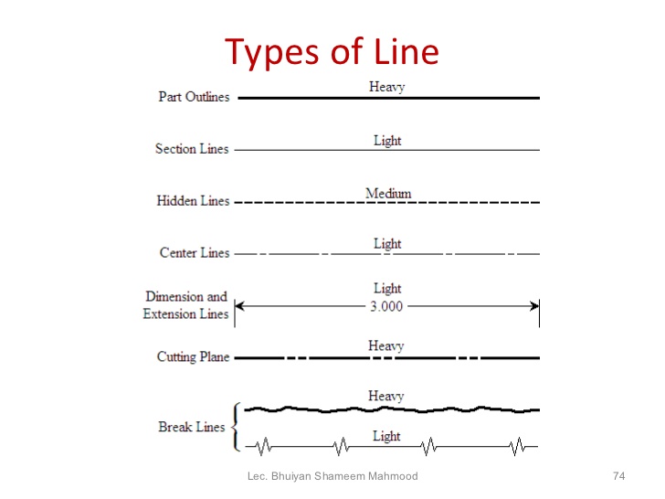
Engineering Drawing 8 Tips to Improve Engineering Drawing Skills

Different Types of LINES in Engineering Drawing//Classification of
How to draw a break line
Types Of Lines In Engineering Drawing

Types of Lines Engineering Drawing MechGate YouTube
AUTOCAD 2020 BREAKLINE SYMBOL HOW TO DRAW BREAK LINE SYMBOL YouTube

Engineering Drawing 2 Ch4 Conventional break YouTube

10 Different Types of Lines Used In Engineering Drawing

DRAWING BASICS
PPT BASIC BLUEPRINT READING PowerPoint Presentation, free download
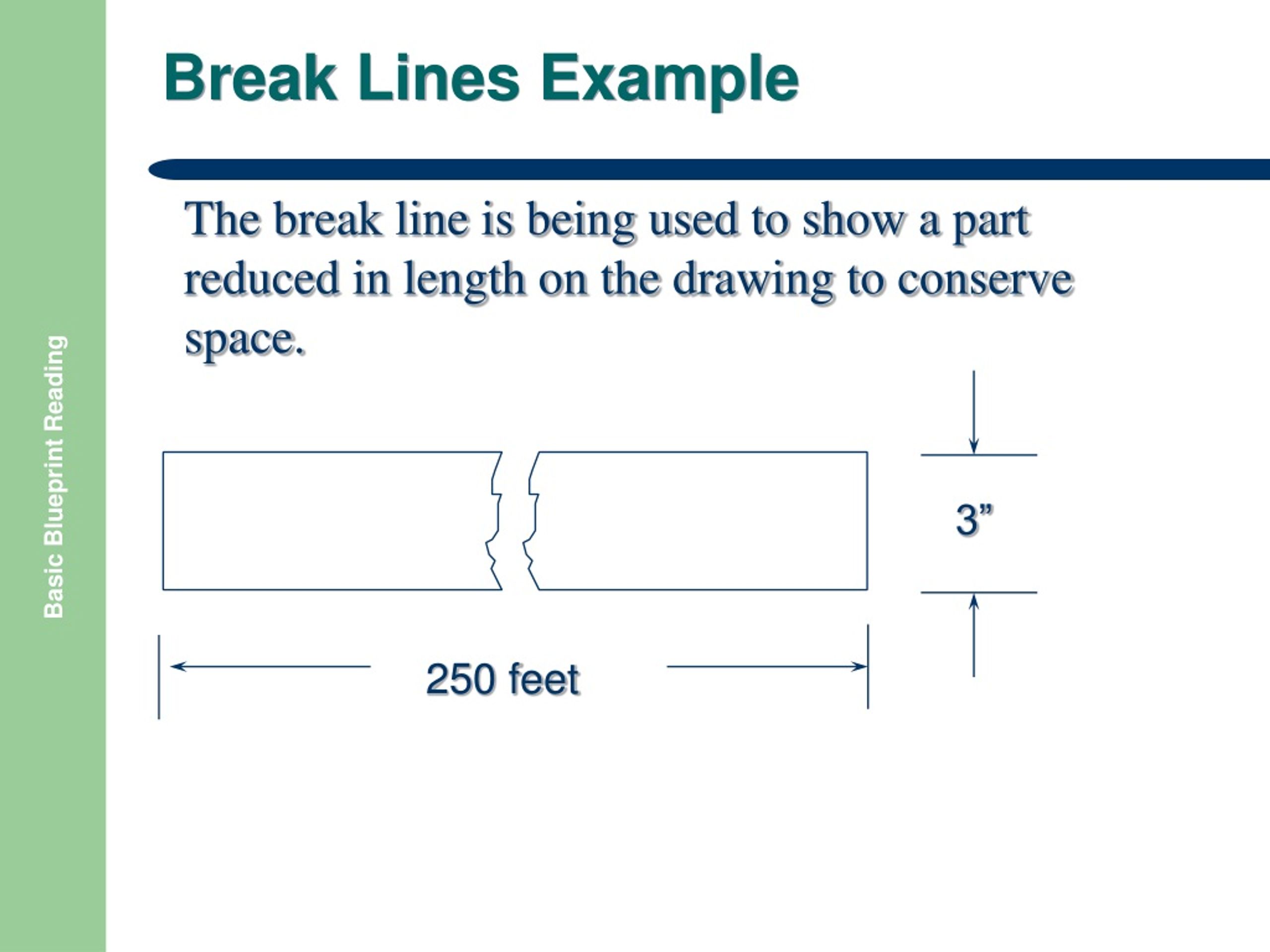
Web Break Lines Are Drawn To Show That A Part Has Been Shortened To Reduce Its Size On The Drawing.
They Are Used To Remove, Or ‘Break Out” Part Of A Drawing For Clarity, And Also To Shorten Objects Which Have The Same Shape Throughout Their Length And May Be Too Long To Place On The Drawing.
They Will Also Be Used To Lay Out The Rest Of Your Drawing.
These Line Types Are Referred To As The Alphabet Of Lines.
Related Post: